Fuel cell

a fuel cell and cell technology, applied in the field of fuel cells, can solve the problems of reducing the pressure of the sealing line (compression load per unit length of the seal), affecting the sealing performance, and introducing foreign materials, etc., and achieve the effect of maintaining the sealing performan

Active Publication Date: 2008-08-07
HONDA MOTOR CO LTD
View PDF1 Cites 9 Cited by
  • Summary
  • Abstract
  • Description
  • Claims
  • Application Information

AI Technical Summary

Benefits of technology

[0012]The present invention has been made to solve the problem, and an object of the present invention is to provide a fuel cell which is not affected by cha

Problems solved by technology

As a result, entry of foreign material, or degradation of the power generation performance or the like may occur easily.
Thus, by the decrease in the compression load applied to the insulating member 4, t

Method used


Image

  • Fuel cell
  • Fuel cell
  • Fuel cell

Examples


Embodiment Construction

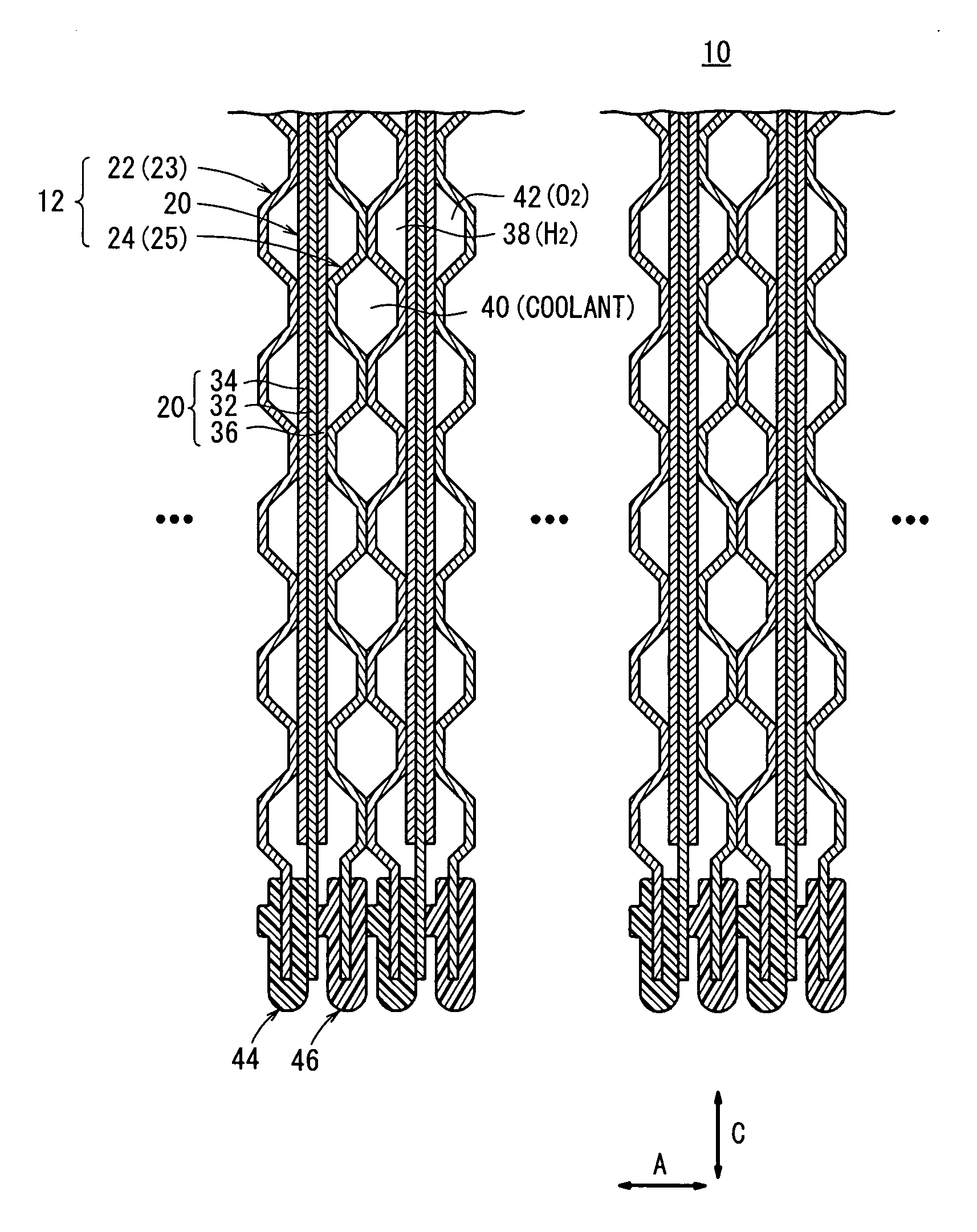
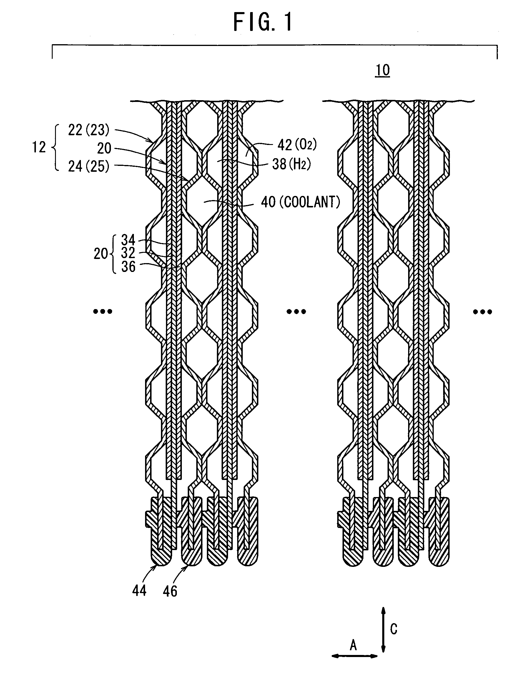
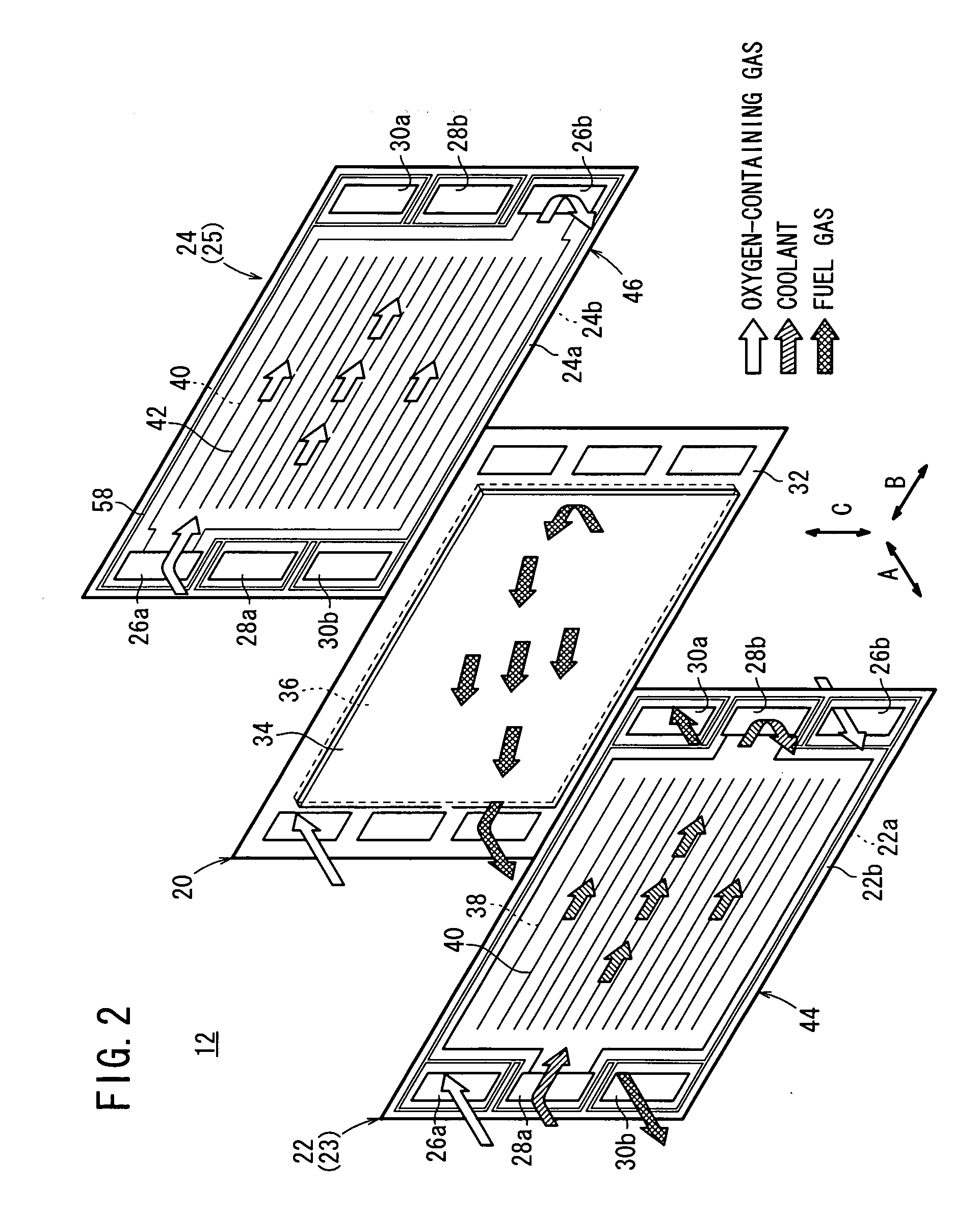
[0023]FIG. 1 is a partial cross sectional side view showing a fuel cell 10 according to an embodiment of the present invention, and FIG. 2 is a partial exploded perspective view showing a power generation cell 12 of the fuel cell 10.

[0024]In the fuel cell 10, a plurality of power generation cells 12 are stacked horizontally in a direction indicated by an arrow A. As shown in FIG. 2, the power generation cell 12 includes a membrane electrode assembly (electrolyte electrode assembly) 20 and first and second metal separators 22, 24 sandwiching the membrane electrode assembly 20. The first and the second metal separators 22, 24 are made of metal plates 23, 25, respectively. Each of the first and the second metal separators 22, 24 is fabricated in a corrugated shape or a dimpled shape under pressure to have ridges and recesses in cross section (see FIGS. 1 and 2).

[0025]At one end of the power generation cell 12 in a longitudinal direction indicated by an arrow B in FIG. 2, an oxygen-cont...


PUM


Abstract

A first metal separator of a fuel cell comprises a metal plate, and a first seal member is formed integrally on both surfaces of an outer edge of the metal plate. A first rib having a frame shape is provided around an oxygen-containing gas supply passage or the like of the metal plate. The first rib has a rib surface spaced away from an inner end surface of the metal plate around the oxygen-containing gas supply passage or the like, toward the oxygen-containing gas supply passage or the like.

Description

BACKGROUND OF THE INVENTION[0001]1. Field of the Invention[0002]The present invention relates to a fuel cell formed by stacking an electrolyte electrode assembly and a separator in a stacking direction. The electrolyte electrode assembly includes a pair of electrodes and an electrolyte interposed between the electrodes. A passage extends through the fuel cell in the stacking direction for allowing at least a reactant gas or a coolant to flow in the stacking direction.[0003]2. Description of the Related Art[0004]For example, a polymer electrolyte fuel cell employs an electrolyte membrane (electrolyte). The electrolyte membrane is a polymer ion exchange membrane. A membrane electrode assembly includes an anode, a cathode, and the electrolyte membrane interposed between the anode and the cathode. Each of the anode and the cathode includes an electrode catalyst and porous carbon. The membrane electrode assembly and separators (bipolar plates) sandwiching the membrane electrode assembly ...

Claims


Application Information

Patent Timeline
IPC IPC(8): H01M8/02H01M50/77
CPCH01M8/0206H01M8/0247Y02E60/50H01M8/0276H01M2008/1095H01M8/0267H01M8/0273H01M8/2483H01M8/0258H01M8/2457H01M8/241
Inventor WATANABE, YASUHIROSAKANO, MASAAKISATO, SHUJIINAI, SHIGERUOHTANI, TERUYUKITAKAHASHI, KEN
Owner HONDA MOTOR CO LTD
Why Eureka
Try Eureka