
Fan speed control from adaptive voltage supply

a technology of adaptive voltage and fan speed control, which is applied in the direction of process and machine control, positive displacement liquid engine, instruments, etc., can solve the problem that the ambient air temperature is not the best measure of the heat of a specific integrated circuit sens

Inactive Publication Date: 2008-08-07
IBM CORP
View PDF51 Cites 17 Cited by
  • Summary
  • Abstract
  • Description
  • Claims
  • Application Information

AI Technical Summary

Benefits of technology

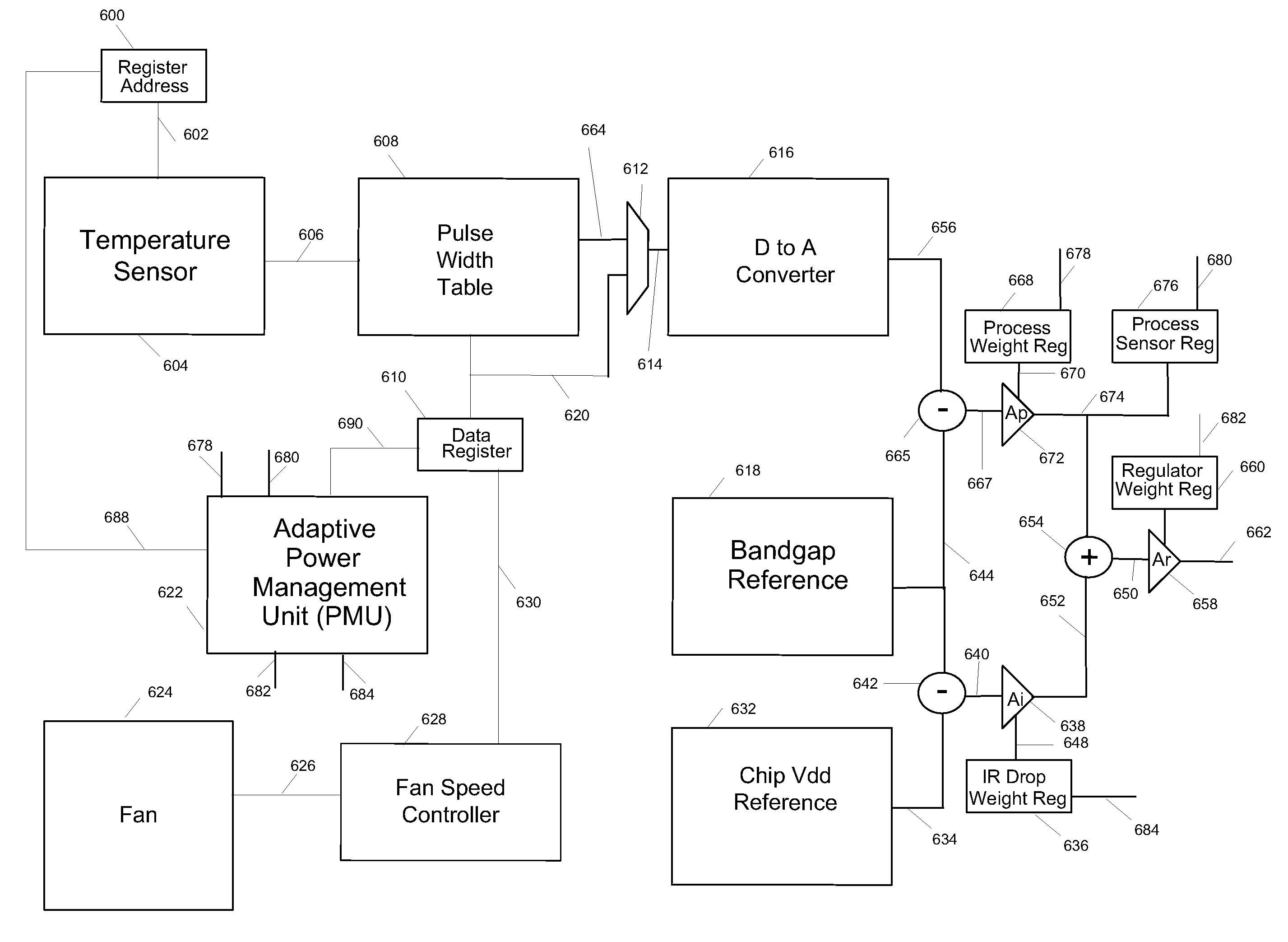
[0009]In one embodiment of the present invention, a method for controlling fan speed, including the steps of measuring temperature using several thermal diodes located upon the surface of a single integrated circuit, and determining if the measured temperatures are with and a predetermined temperature range, where the average of the temperatures is used to control the fan speed.

Problems solved by technology

However, the ambient air temperature is not the best measure of the heat of a specific integrated circuit sense.

Method used


Image

  • Fan speed control from adaptive voltage supply
  • Fan speed control from adaptive voltage supply
  • Fan speed control from adaptive voltage supply

Examples


Embodiment Construction

[0019]The following is intended to provide a detailed description of an example of the invention and should not be taken to be limiting of the invention itself. Rather, any number of variations may fall within the scope of the invention, which is defined in the claims following the description.

[0020]The present invention provides a cooling mechanism including a fan speed controller that operates off of data obtained from an adaptive voltage system. The adaptive voltage system is contained upon the integrated circuit surface itself. In one embodiment of the invention, individual and adaptive voltage systems are contained within each core of a Baltic or integrated circuit. A common application would provide an integrated circuit having multiple CPUs, where each CPU is a core. Each of the adaptive voltage systems contained within each core would provide an input to a fan speed controller that would be connected to a fan to provide cooling for the computer system or for the individual i...


PUM


Abstract

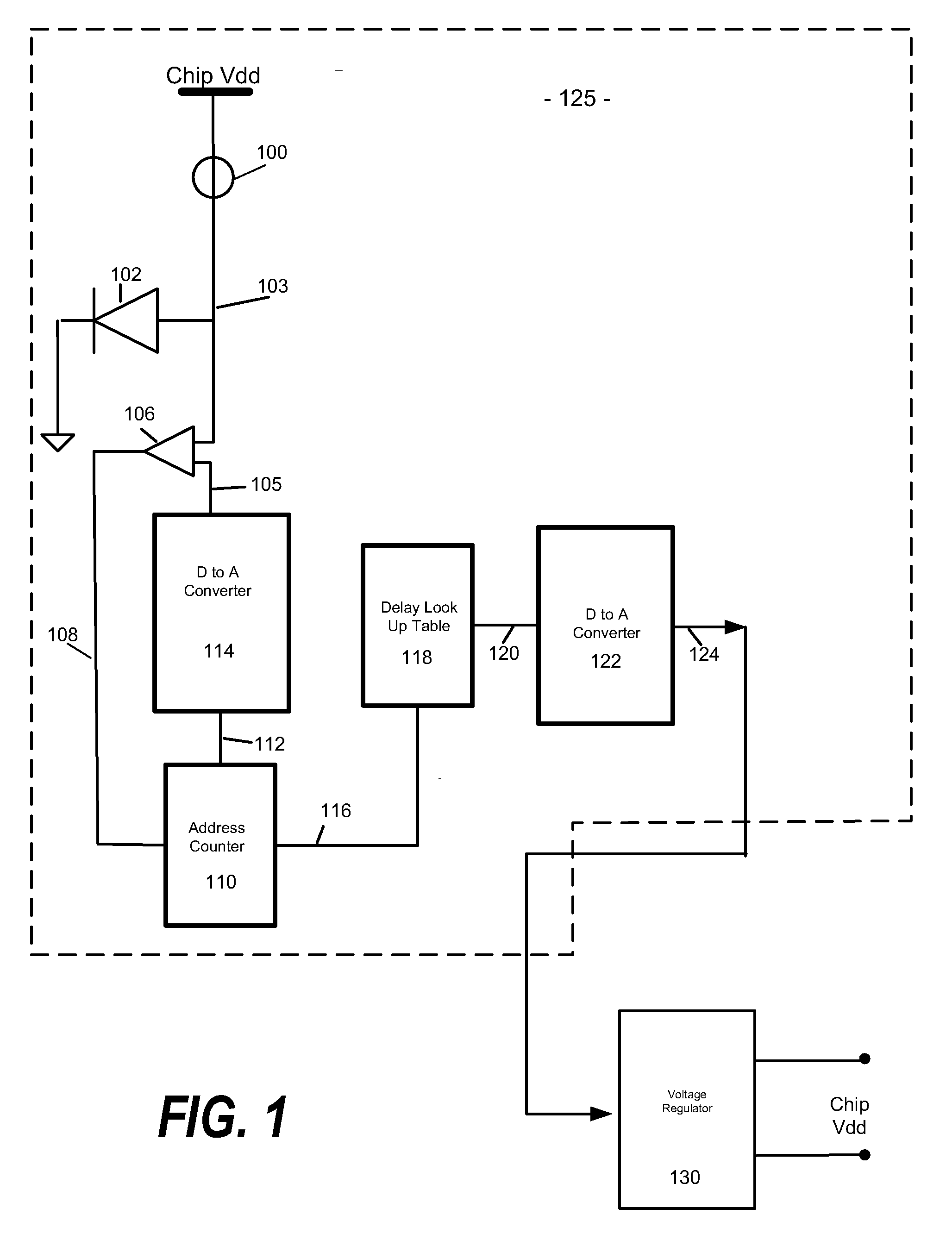
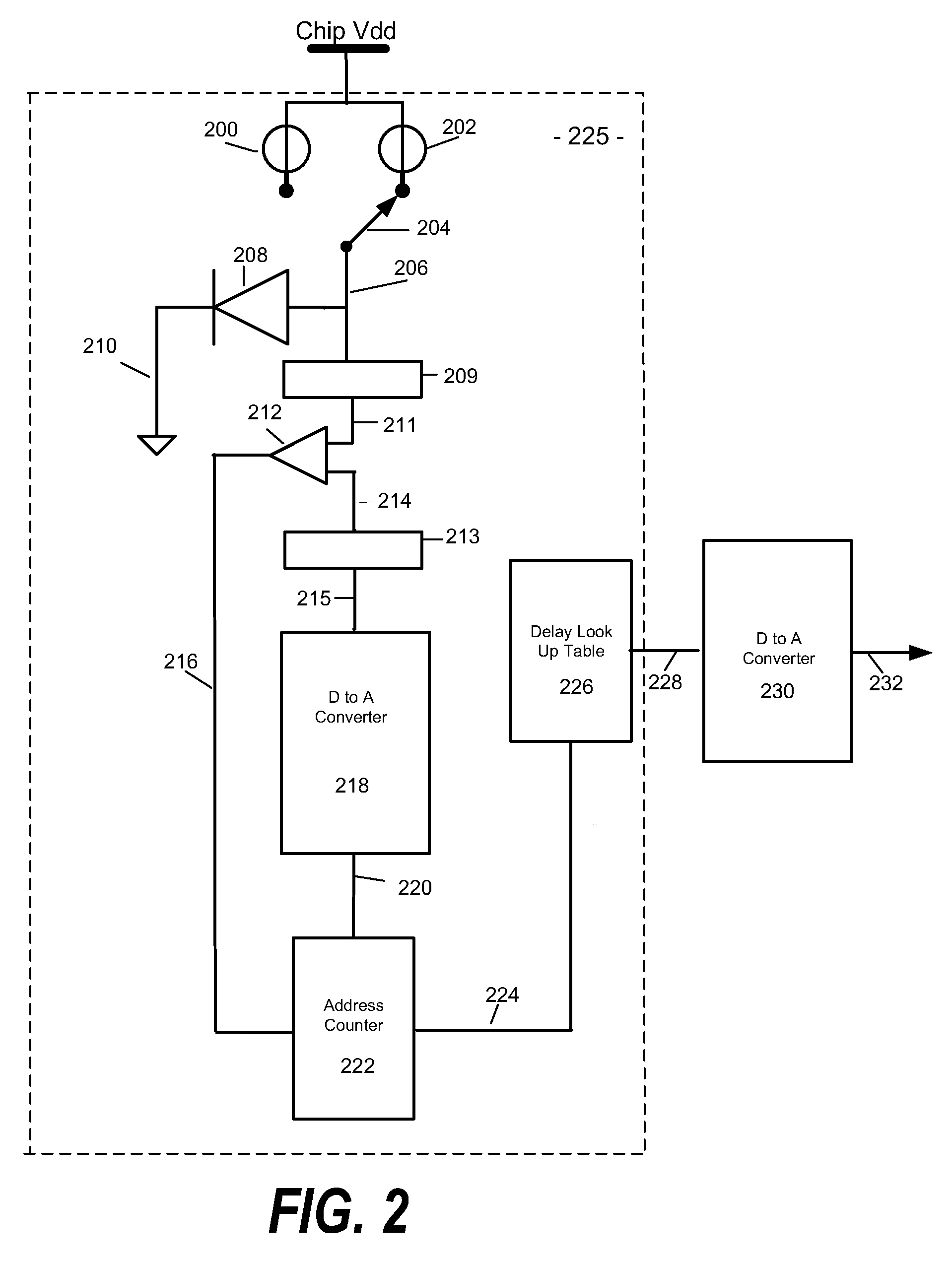
Measurement circuit components are included in an integrated circuit fabricated on a semiconductor substrate. A method is provided for controlling the speed of a cooling fan provided to cool an integrated circuit in which includes the steps of receiving a voltage from a thermal diode, addressing a table of digital temperatures by incrementing the address of the table entries every clock cycle of a circuit clock, converting the addressed data to a second voltage representing temperature, comparing the first voltage to the second voltage, providing a resulting temperature when both the first and second voltages are equal, and adjusting the fan speed accordingly.

Description

RELATED APPLICATIONS[0001]This application is related to the following co-pending U.S. patent applications filed on the same day as the present application and having the same assignee: “On-Chip Adaptive Voltage Compensation,” (Docket No. RPS9 2006 0231 US1); “Using Temperature Data for Instruction Thread Direction,” (Docket No. RPS9 2006 0263 US1); “Using Performance Data for Instruction Thread Direction,” (Docket No. RPS9 2006 0262 US1); “Using IR Drop Data for Instruction Thread Direction,” (Docket No. RPS9 2006 0261 US1); “Integrated Circuit Failure Prediction,” (Docket No. RPS9 2006 0260 US1); “Instruction Dependent Dynamic Voltage Compensation,” (Docket No. RPS9 2006 0259 US1); “Temperature Dependent Voltage Source Compensation,” (Docket No. RPS9 2006 0258 US1); and “Digital Adaptive Voltage Supply,” (Docket No. RPS9 2006 0256 US1); each assigned to the IBM Corporation and herein incorporated by reference.BACKGROUND OF THE INVENTION[0002]1. Technical Field[0003]The present inv...

Claims


Application Information

Patent Timeline
Patent Type & Authority Applications(United States)
IPC IPC(8): G05D23/19F04B49/20
CPCF04D27/004Y02B30/70
Inventor SINGH, DEEPAK K.ATALLAH, FRANCOIS IBRAHIMALLEN, DAVID HOWARD
Owner IBM CORP
Learn More