Manufacturing method for micro-nano bubble bathtub water and micro-nano bubble bathtub

a manufacturing method and technology for bathtubs, applied in baths, douches, physical therapy, etc., can solve the problems of limited effect on human body, increased cost of bathtubs, leg amputation, etc., and achieve the effect of wide size distribution and easy production

Inactive Publication Date: 2008-08-14
SHARP KK
View PDF2 Cites 35 Cited by
  • Summary
  • Abstract
  • Description
  • Claims
  • Application Information

AI Technical Summary

Benefits of technology

[0048]In the micro-nano bubble bathtub in the present embodiment, a bath agent is added to the bathtub section so that ideal bathtub water containing micro-nano bubbles can be manufactured.
[0049]According to the manufacturing method for micro-nano bubble bathtub water in the present invention, micro-nano bubbles having a wide size distribution can be generated by generating micro-nano bubbles different in size distribution in the upper part and the lower part of the micro-nano bubble generation section. B...

Problems solved by technology

However, in bathtubs using one kind of micro-nano bubble generators, the size range of generated micro-nano bubbles was small, and so the effect on human body, especially the extent of the influence on the flow of blood was limited.
There ...

Method used


Image

  • Manufacturing method for micro-nano bubble bathtub water and micro-nano bubble bathtub
  • Manufacturing method for micro-nano bubble bathtub water and micro-nano bubble bathtub
  • Manufacturing method for micro-nano bubble bathtub water and micro-nano bubble bathtub

Examples


first embodiment

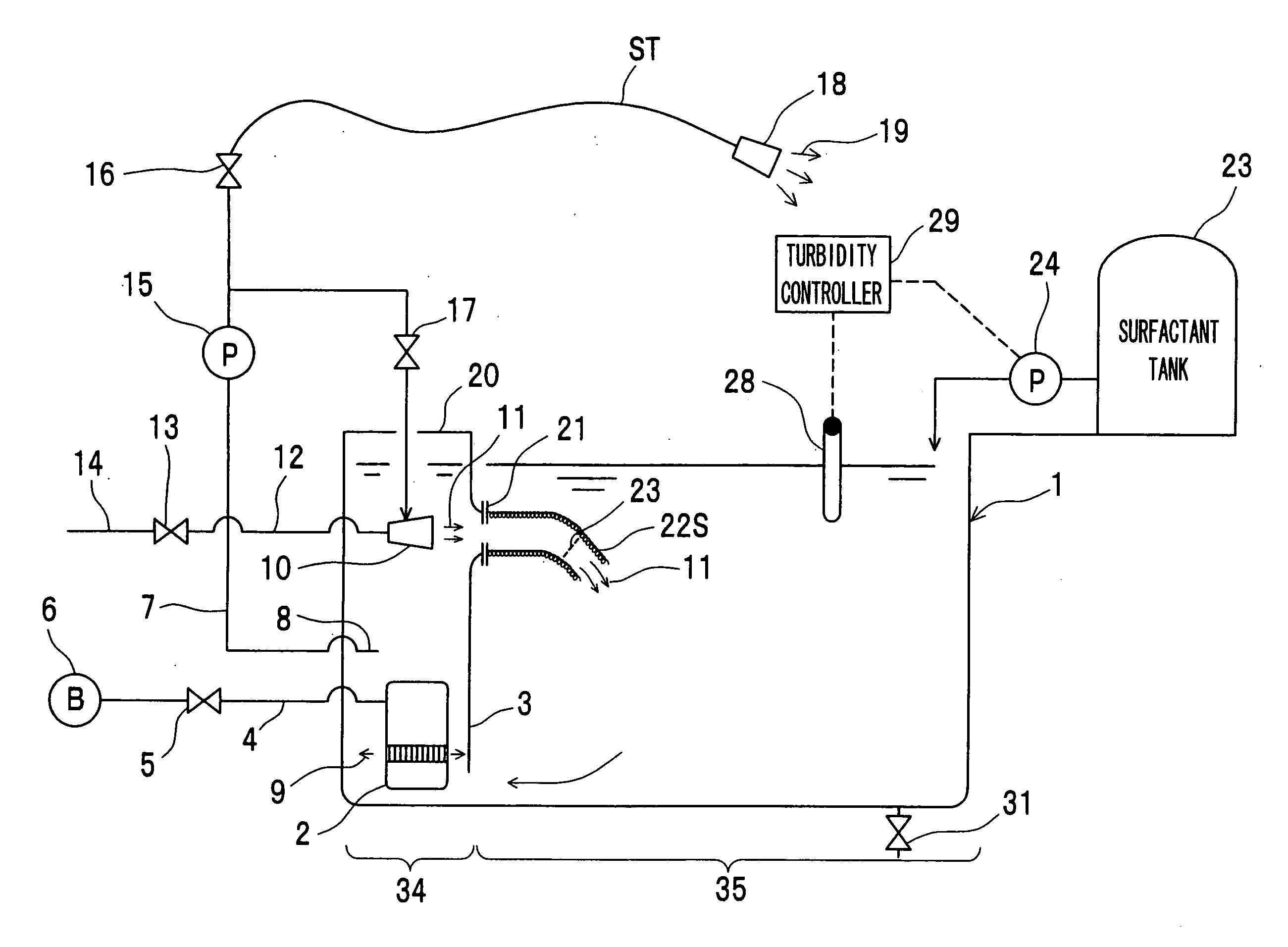
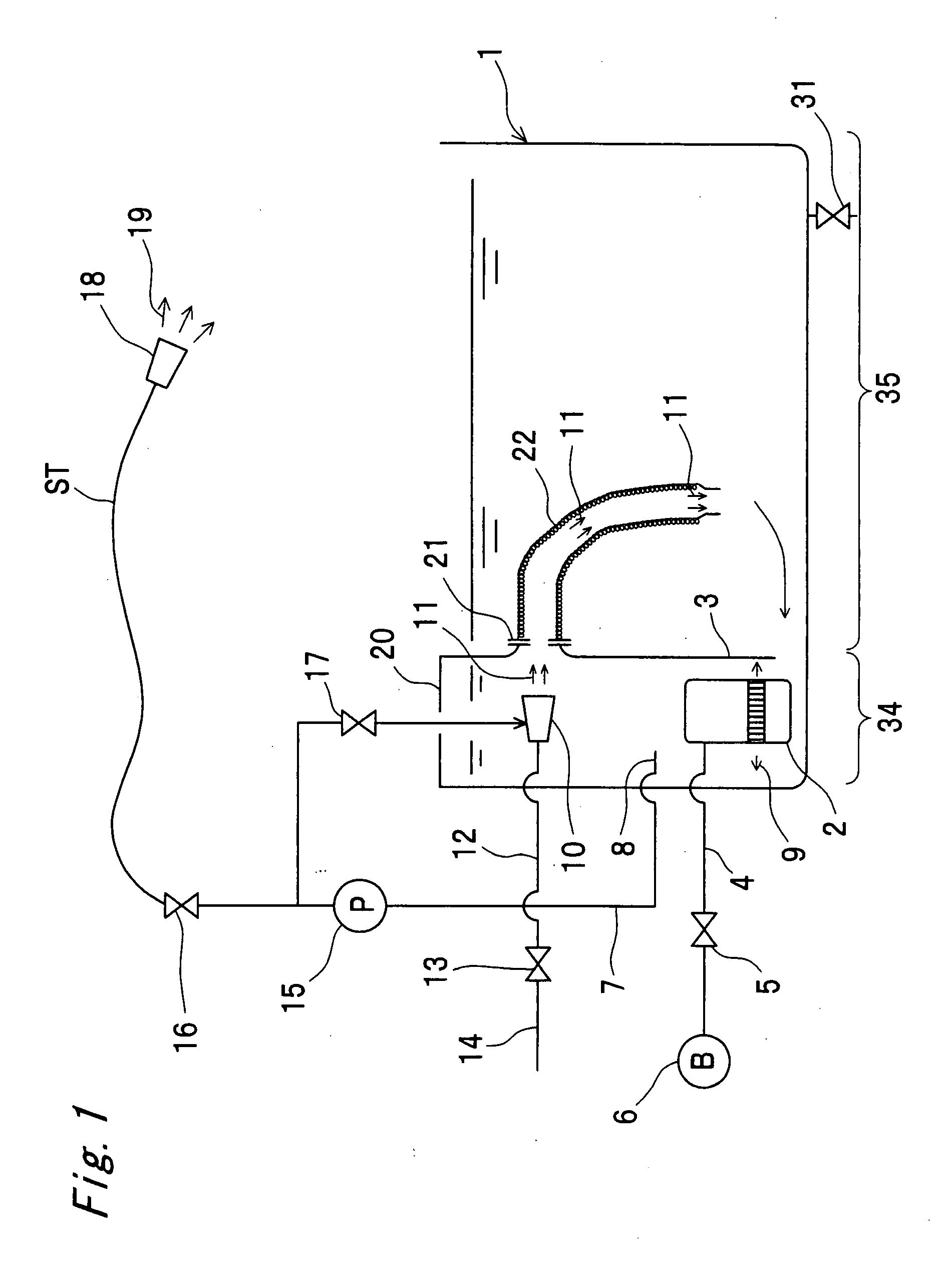
[0063]FIG. 1 is a schematic view showing a first embodiment of a micro-nano bubble bathtub in the present invention. The micro-nano bubble bathtub 1 includes a micro-nano bubble generation section 34 and a bathtub section 35. Although the micro-nano bubble generation section 34 and the bathtub section 35 are partitioned with a partition wall 3, the micro-nano bubble generation section 34 and the bathtub section 35 are connected at the lower end of the partition wall 3.

[0064]The micro-nano bubble generation section 34 has, from the bottom side, a submerged pump-type micro-nano bubble generator 2 having a blower 6, a suction tube 8 connected to a circulating pump 15, and a spiral flow-type micro-nano bubble generator 10 connected to the circulating pump 15 through a pipe 7. The micro-nano bubble generation section 34 has an equipment section covering 20 placed above the spiral flow-type micro-nano bubble generator 10 as a micro-nano bubble generator involving high-speed whirling.

[0065...

second embodiment

[0085]Next, FIG. 2 shows a second embodiment of a micro-nano bubble bathtub in the present invention. The second embodiment is different from the above-mentioned first embodiment in the point that a bellow hose 22S shorter than the bellow-like hose 22 of the first embodiment in FIG. 1 is provided, the point that a small perforated plate 33 placed in the bellow-like hose 22S is provided, and the point that a turbidimeter 28 placed in the micro-nano bubble bathtub 1, and a turbidity controller 29, a surfactant tank metering pump 24 and a surfactant tank 23 in cooperation with the turbidimeter 28 are newly provided.

[0086]Therefore, in this second embodiment, component members identical to those in the first embodiment are designated by identical reference numerals to omit detailed description, and description will mainly be given of the portions different from the first embodiment.

[0087]As shown in FIG. 2, since the bellow hose 22S shorter than the bellow-like hose 22 in first embodime...

third embodiment

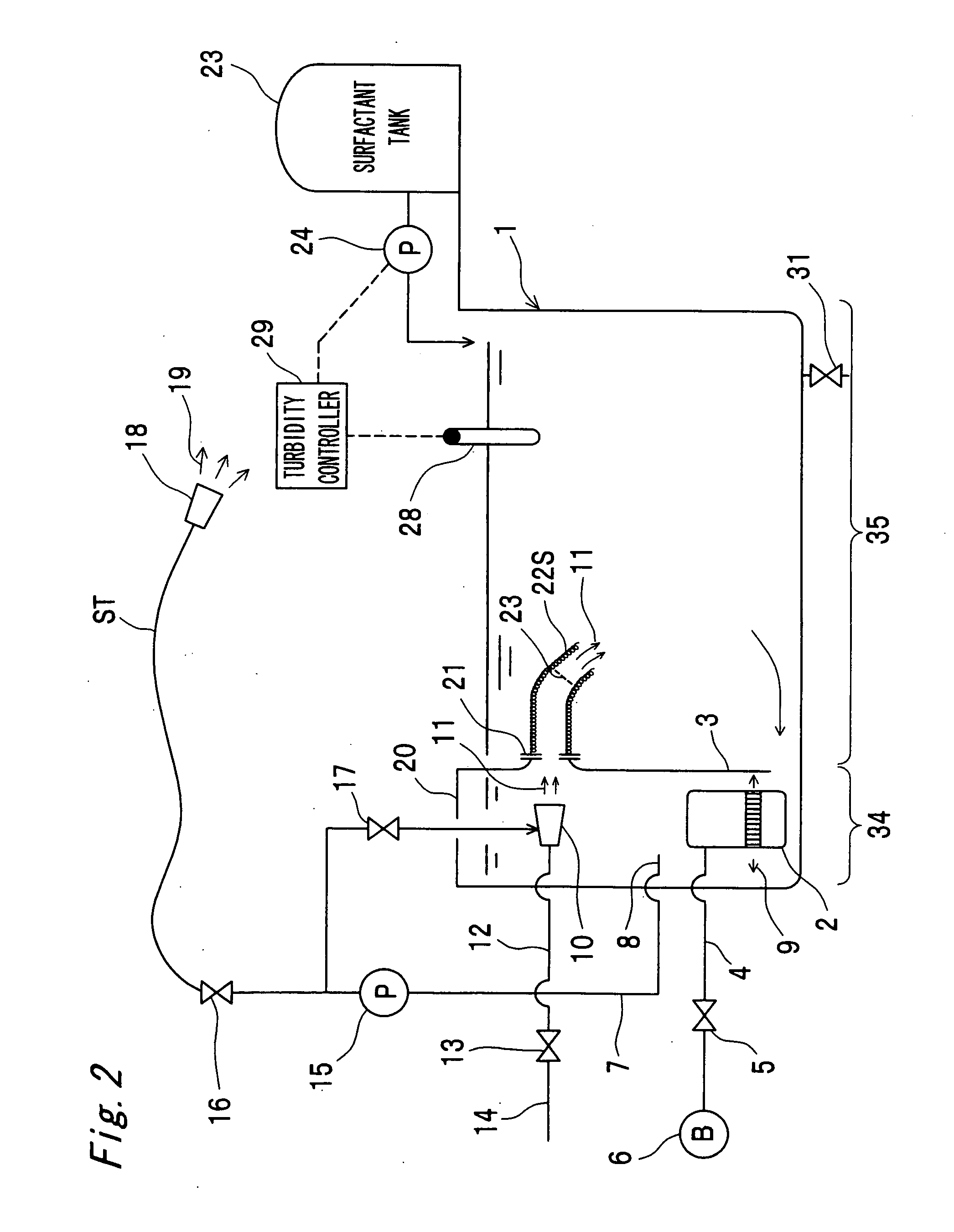
[0090]Next, FIG. 3 shows a third embodiment of a micro-nano bubble bathtub in the present invention. The third embodiment is different from the above-mentioned first embodiment in the point that the valve 16 in the shower section of the first embodiment in FIG. 1 is not connected to the pipe 7 but connected to a newly placed shower pump 25. Therefore, in this third embodiment, component members identical to those in the first embodiment in FIG. 1 are designated by identical reference numerals to omit detailed description, and description will mainly be given of the portions different from the first embodiment.

[0091]In the third embodiment, the shower pump 25 can pump bathtub water containing micro-nano bubbles above the spiral flow-type micro-nano bubble generator 10 in the upper part of the micro-nano bubble generation section 34 to the valve 16 from a pipe L2 via a pipe L1, and can sprinkle the bathtub water as shower water 19 from the shower outlet 18 through the shower tube ST.

[...


PUM


Abstract

In the upper part and the lower part of a micro-nano bubble generation section 34 in a micro-nano bubble bathtub 1, two kinds of micro-nano bubbles different in a size distribution are generated by first and second micro-nano bubble generators (submerged pump-type micro-nano bubble generator 2 and spiral flow-type micro-nano bubble generator 10) of two kinds, so that bathtub water containing micro-nano bubbles in a wide size distribution can be produced in a large amount. Some of the water containing micro-nano bubbles generated in the lower part is thrown into the first micro-nano bubble generator (spiral flow-type micro-nano bubble generator 10) in the upper part, so that the spiral flow-type micro-nano bubble generator 10 can generate micro-nano bubbles in a smaller size. Therefore, in this bathtub, micro-nano bubbles abundant in size and large in amount can be produced economically.

Description

CROSS REFERENCE OF RELATED APPLICATION[0001]This nonprovisional application claims priority under 35 U.S.C. §119(a) on Patent Application No(s). 2006-264171 filed in Japan on Sep. 28, 2006, the entire contents of which are hereby incorporated by reference.BACKGROUND OF THE INVENTION[0002]The present invention relates to a manufacturing method for micro-nano bubble bathtub water and a micro-nano bubble bathtub utilizing two kinds of micro-nano bubble generators.[0003]Conventionally, there were bathtubs using micro-nano bubble generators. However, in bathtubs using one kind of micro-nano bubble generators, the size range of generated micro-nano bubbles was small, and so the effect on human body, especially the extent of the influence on the flow of blood was limited.[0004]There are many diabetics particularly in Japan, and there are some cases of leg amputation due to gangrene caused by deteriorated blood-flow near the tips of extremities. Although a bathtub system generating micro-na...

Claims


Application Information

Patent Timeline
IPC IPC(8): A61H33/02
CPCA61H33/02A61H33/027A61H33/6073A61H33/6026A61H33/6036A61H2033/0037
Inventor YAMASAKI, KAZUYUKISAKATA, KAZUYUKICHUHJOH, KAZUMIKATAOKA, MASAKI
Owner SHARP KK
Why Eureka
Try Eureka