Furnace hearth compression

Inactive Publication Date: 2008-08-14
MACRAE TECH
View PDF11 Cites 3 Cited by
  • Summary
  • Abstract
  • Description
  • Claims
  • Application Information

AI Technical Summary

Benefits of technology

[0008]An advantage of the present invention is that replacement of the furnace hearth and the surrounding expansion material is less frequent compared to conventional systems.
[0009]Another advantage of the present invention is that a system is provided that reduces the rate of expansion of the furnace hearth by increasing the load on the furnace hearth.
[0010]A further advantage of the present invention is conventional containment shells can be modified so the thrust blocks and rods of the present invention can be readily installed and put to work.
[0011]A still further advantage of the present invention is that a system is provided such that a hearth binding system could also be installed on rectangular furnaces with flexible binding systems, which already

Problems solved by technology

The loose plate construction can accommodate some growth in the hearth bricks that occurs as the bricks each slowly absorb molecules of metal over their operational lifetimes. The conventional means of binding the shell plates together, and that maintain a correct compressive force

Method used


Image

  • Furnace hearth compression
  • Furnace hearth compression
  • Furnace hearth compression

Examples


Embodiment Construction

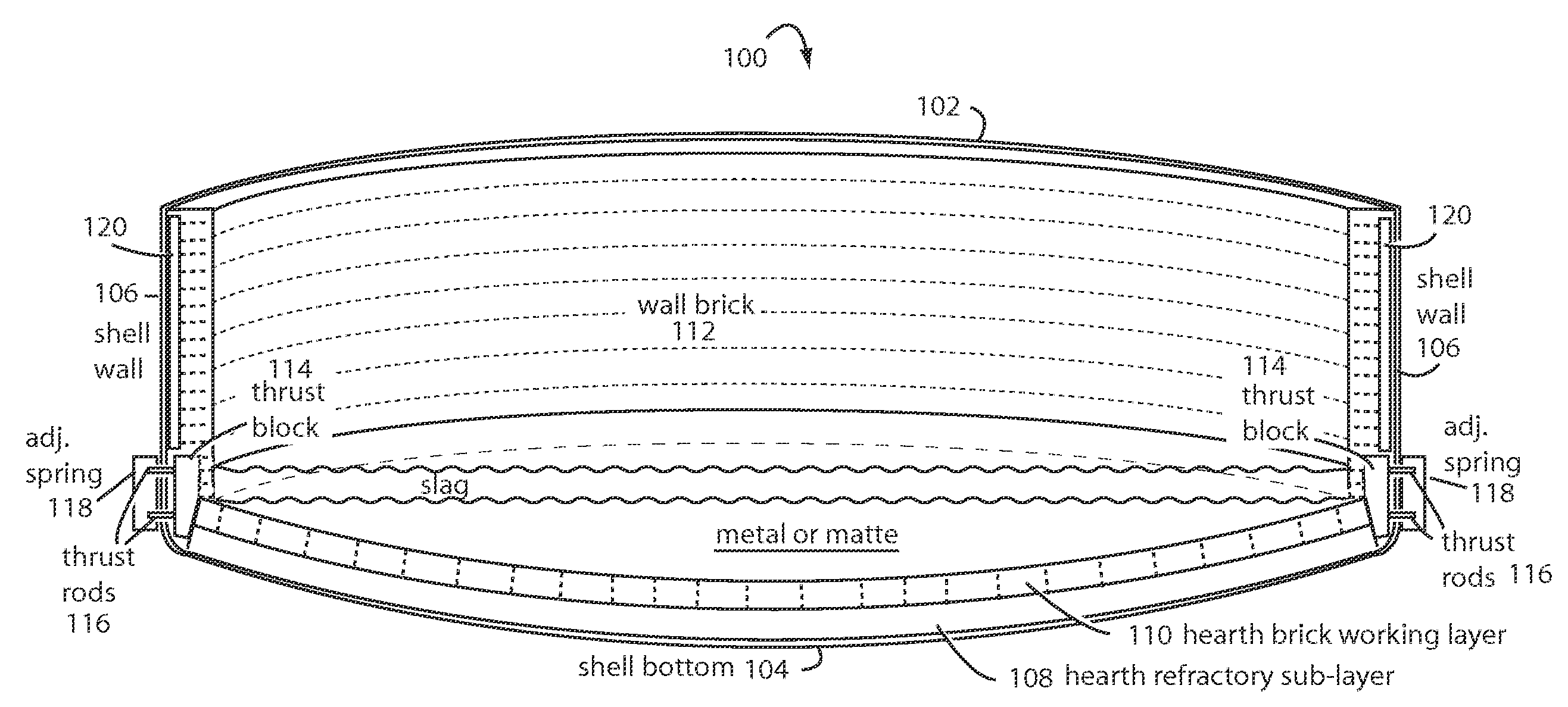
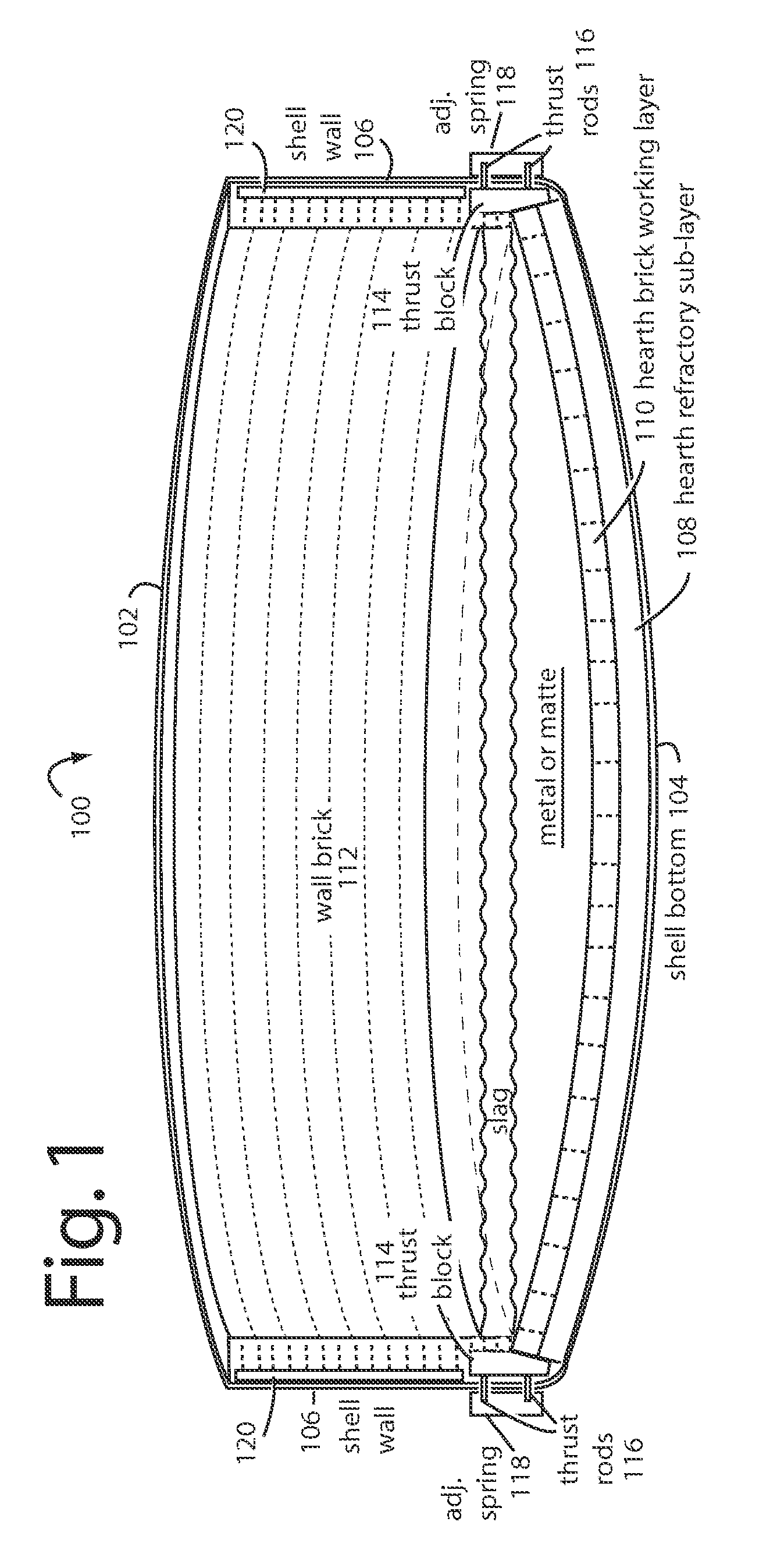
[0020]FIG. 1A represents a furnace refractory brick hearth system embodiment of the present invention, and is referred to herein by the general reference numeral 100. The system 100 comprises an outer, rigid steel containment shell 102 having a dished bottom 104 and circular vertical walls 106. The bottom is lined with hearth refractory in one or more sub-layers like sub-layer 108, over which is placed a hearth brick working layer 110. Such hearth refractory may comprise individual bricks.

[0021]The outer perimeter of the hearth brick working layer 110 supports a wall brick 112. Gravity keeps the wall brick 112 tightly packed, and a ring of thrust blocks 114 inwardly compress and compact the hearth brick working layer 110. The radial compression towards the center is provided by many individual thrust rods 116 that each push inwardly against corresponding thrust blocks 114. The thrust rod forces are provided externally by adjustable spring assemblies 118 mounted on the outside of the...


PUM

PropertyMeasurementUnit
Forceaaaaaaaaaa
Pressureaaaaaaaaaa
Diameteraaaaaaaaaa

Abstract

A brick hearth system comprises a rigid containment shell in which a concave bottom is lined with a hearth refractory sub-layer and hearth brick working layer. The outer perimeter of the hearth refractory is ringed with thrust blocks to compress the whole toward the center and to thereby deny gaps from forming between the separate bricks. Many individual thrust rods penetrate the outer bottom of the containment shell, and such are used to transmit compression forces generated outside the shell to be applied against the thrust blocks in unison. Each thrust rod receives an adjustable amount of inward force from a spring, acting either directly or through a beam or rocker arm. These are anchored to and use the hoop strength of the containment shell as leverage. As the hearth brick working layer grows during its service life, the ring of thrust blocks grows in diameter as well inside the margins provided within the containment shell. The individual thrust rod springs are periodically adjusted to keep the pressures in the optimal range.

Description

BACKGROUND[0001]1. Field of the Invention[0002]The present invention relates to pyrometallergical furnaces for the smelting, converting, or melting of concentrates, mattes, or metals, and more particularly to methods and devices for applying and maintaining proper compression of the brick hearth in a furnace refractory so as to extend its service life.[0003]2. Description of the Prior Art[0004]Layers of refractory bricks inside a tub-like shell are needed to cover the floor interior with a hearth sub-layer and brick hearth working layer, and to line the interior of the walls. The refractory brick layers inside the steel shell can withstand the very high operating temperatures, and the shell provides the necessary containment and support.[0005]Some so-called flexible shells are constructed with adjoining plates that are bound together. The loose plate construction can accommodate some growth in the hearth bricks that occurs as the bricks each slowly absorb molecules of metal over the...

Claims


Application Information

Patent Timeline
IPC IPC(8): F23M5/04F23M5/00F23M5/08
CPCF23M5/04F27D1/0023F27B3/14F23M2900/05002
Inventor MACRAE, ALLAN J.
Owner MACRAE TECH
Why Eureka
Try Eureka