Valve train assembly with magnet

a technology of valve train and magnet, which is applied in the direction of valve arrangement, machine/engine, pressure lubrication, etc., can solve the problems of filter and screen blockage, etc., and achieve the effect of preventing the failure of hydraulic lash adjuster and preventing the blockage of the screen used

Inactive Publication Date: 2008-08-14
FCA US +1
View PDF9 Cites 13 Cited by
  • Summary
  • Abstract
  • Description
  • Claims
  • Application Information

AI Technical Summary

Benefits of technology

[0008]It is an object of the Invention to prevent failure of hydraulic lash adjusters from m...

Problems solved by technology

In each of these arrangements, the hydraulic lash adjuster is the end of an oil passageway and metal particles which are contained within the oil can collect in the hydraulic lash adjuster and cause failure of the hydraulic lash adjuster.
Such failure usually occurs when the metal particles find their way from the low pressure cavity to the high pressure cavity and jam the moving mechanisms of th...

Method used


Image

  • Valve train assembly with magnet
  • Valve train assembly with magnet
  • Valve train assembly with magnet

Examples


Embodiment Construction

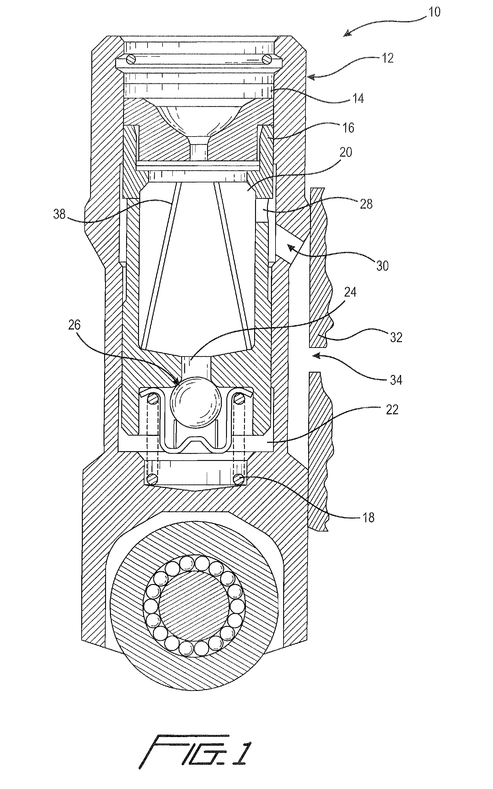
[0033]FIG. 1 illustrates hydraulic lash adjuster 10 having body 12 with blind bore 14. Plunger 16 is slidably positioned within blind bore 14 and is urged outward by spring 18. Low pressure cavity 20 is formed in plunger 16 and high pressure cavity 22 is formed between the bottom of blind bore 14 and the bottom of plunger 16. Valve opening 24 is formed in the bottom of plunger 16 and check valve 26 is positioned to selectively open and close valve opening 24.

[0034]Low pressure cavity 20 and high pressure cavity 22 form an internal oil cavity in the hydraulic lash adjuster.

[0035]Oil enters low pressure cavity 20 through aperture 28 in the side wall of plunger 16. Oil flows to aperture 28 from inlet 30 in the side wall of body 12. Oil flows to inlet 30 through an outlet in the side wall of conduit 32 as shown by arrow 34.

[0036]As illustrated in FIG. 1, low pressure cavity 20 can also employ a screen 38 to collect metal particles from the oil.

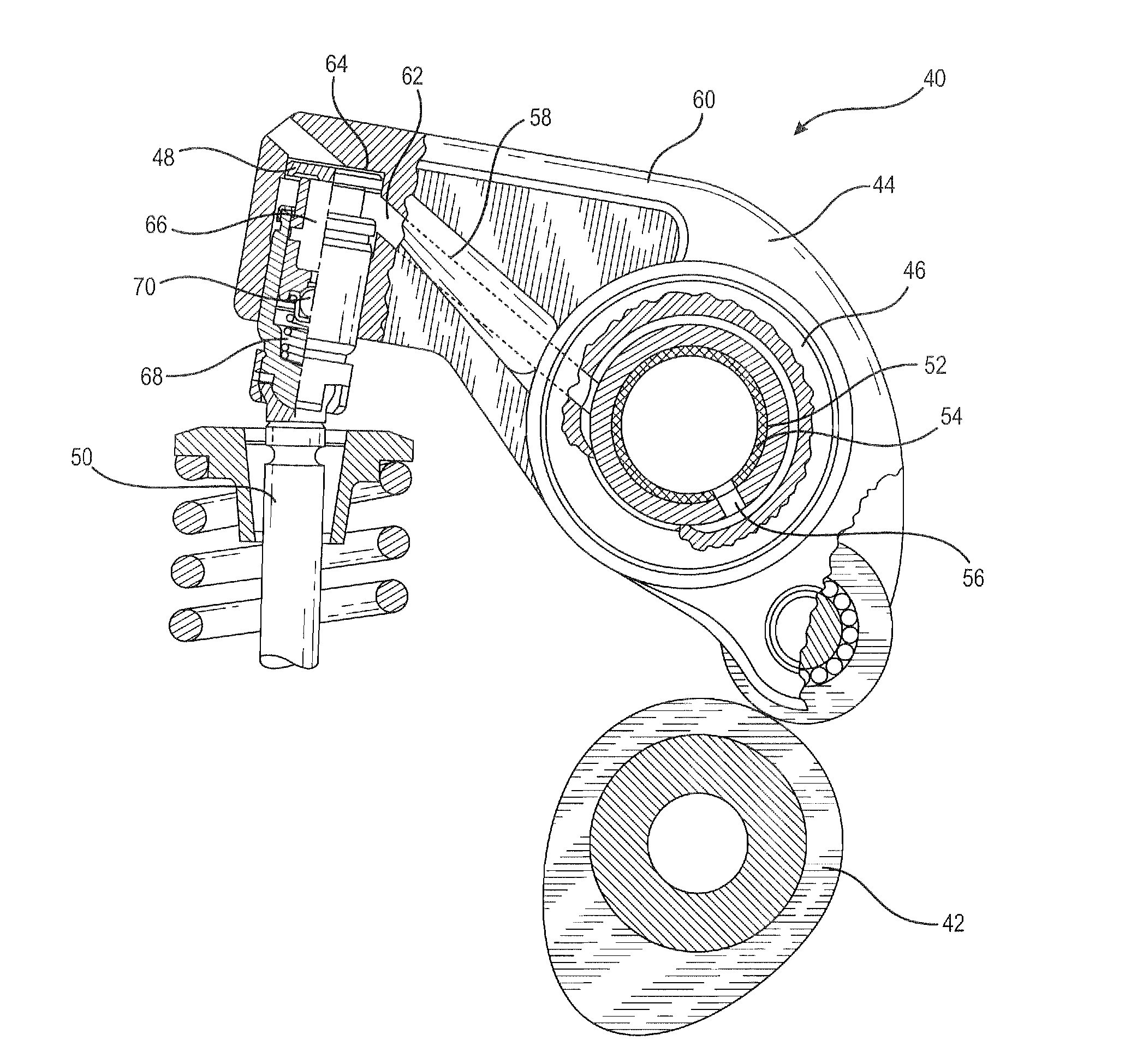
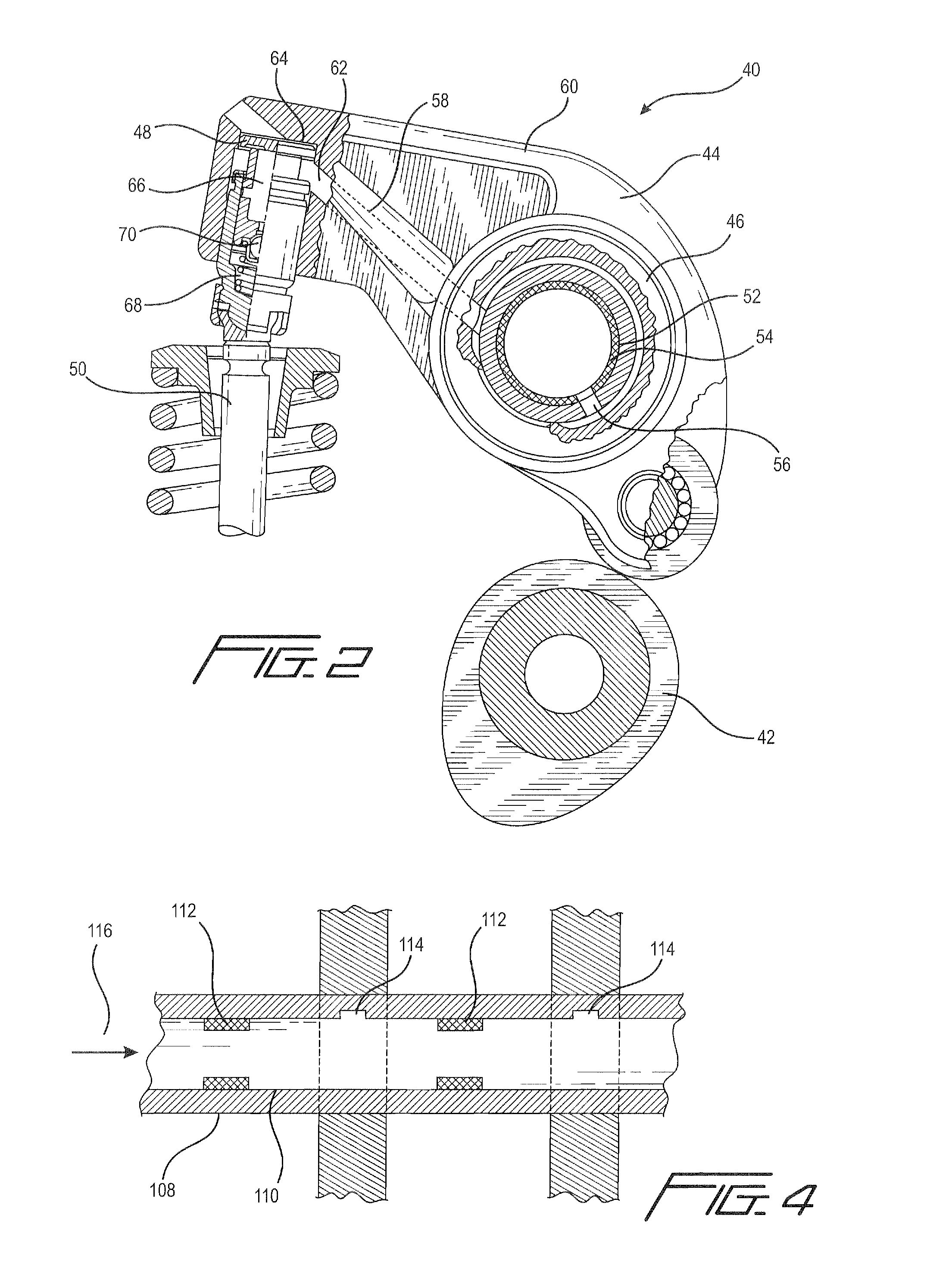
[0037]FIG. 2 illustrates valve train 40 for...


PUM


Abstract

The valve train assembly with magnet uses the magnet to collect ferrous metal particles that are in the oil prior to their arrival at the high pressure cavity of the hydraulic lash adjuster. The magnet can be positioned in the low pressure cavity of the hydraulic lash adjuster, in the bore of the hollow rocker arm shaft or in the bore of the hollow push rod.

Description

FIELD OF THE INVENTION[0001]This Invention relates to internal combustion engines and, more particularly, to valve trains and hydraulic lash adjusters used in internal combustion engines.BACKGROUND OF THE INVENTION[0002]Valve trains of internal combustion engines have a variety of components depending on the design of the engine, however, most modern valve trains have a valve with its associated valve stem, a hydraulic lash adjuster and a cam which actuates the valve through the valve stem.[0003]Hydraulic lash adjusters need oil to function. Hydraulic lash adjusters have a low pressure cavity that acts as an oil reservoir and a high pressure cavity that is fed oil through a check valve positioned between the low pressure and the high pressure cavities. Typically, oil is fed to the hydraulic lash adjuster either through an inlet in the side wall or through an inlet in the top wall of the hydraulic lash adjuster. The inlet of the hydraulic lash adjuster is in fluid communication with ...

Claims


Application Information

Patent Timeline
IPC IPC(8): F01L1/245
CPCF01L1/146F01L1/2411F01M2001/1042F01L1/255F01L2001/3444F01L1/2416
Inventor MCELWEE, MARKJONES, JERMELSAILER, PETERSCHNELL, OLIVER
Owner FCA US
Why Eureka
Try Eureka