Mechanical pulping refiner plate having curved refining bars with jagged leading sidewalls and method for designing plates

a technology of refining bars and refiner plates, which is applied in the field of disc refiners, can solve the problems of mechanical pulping process, reduce the energy efficiency of the refining process, and less desirable, and achieves the effects of reducing the cutting of fibers in the feed material, reducing the cutting of fibers, and long serving plate li

Active Publication Date: 2008-08-14
ANDRITZ INC
View PDF15 Cites 24 Cited by
  • Summary
  • Abstract
  • Description
  • Claims
  • Application Information

AI Technical Summary

Benefits of technology

[0009]A novel refiner plate has been developed to improve energy efficiency, while maintaining a large operating gap between refiner plates on opposing discs. Advantages of the refiner include high energy efficiency, maintaining high fiber quality, and long operating life of the plates.
[0010]In one embodiment, the refiner plate is an assembly of rotor plate segments having an outer refining zone with refining bars that have at least a radially outward refining section with a curved longitudinal shape to form large holdback angle at the outer plate periphery of at least thirty (30) degrees and preferably angles of 45, 60 and 70 degrees. The leading sidewalls of the refining bars have surfaces that are serrated, jagged or otherwise irregular. The bars with irregular surfaces on the sidewalls and large holdback angles increase the retention time of feed material in the outer refining zone and thereby increase the refining of the fibrous material by the outer zone.

Problems solved by technology

The refining action imparted by the bars and grooves may also generate some cutting of the fibers, which is usually a less desirable result of the mechanical pulping process.
In the mechanical pulping refining process, a large amount of friction occurs that reduces the energy efficiency of the refining process.
These techniques often result in reducing the thickness of the fibrous pad in the gap between the opposing plates.
A drawback to reducing the thickness of the fiber pad are that the operating gaps between the refiner plate bars is reduced.
Reducing the gap between the opposing refiner plate bars often results in an increase in fiber cutting, a loss in pulp strength properties due to the cut fibers, and a reduction in the operating life of the refiner plates due to the excessive wear of plates.
A narrow gap, e.g., clearance between bars on opposing plates, may achieve a higher compression ratio and higher efficiency but suffers a reduced operational life.
Reducing the operating refining gaps results in an increase in the wear rate of the refiner plates and shorter plate life.

Method used


Image

  • Mechanical pulping refiner plate having curved refining bars with jagged leading sidewalls and method for designing plates
  • Mechanical pulping refiner plate having curved refining bars with jagged leading sidewalls and method for designing plates
  • Mechanical pulping refiner plate having curved refining bars with jagged leading sidewalls and method for designing plates

Examples


Embodiment Construction

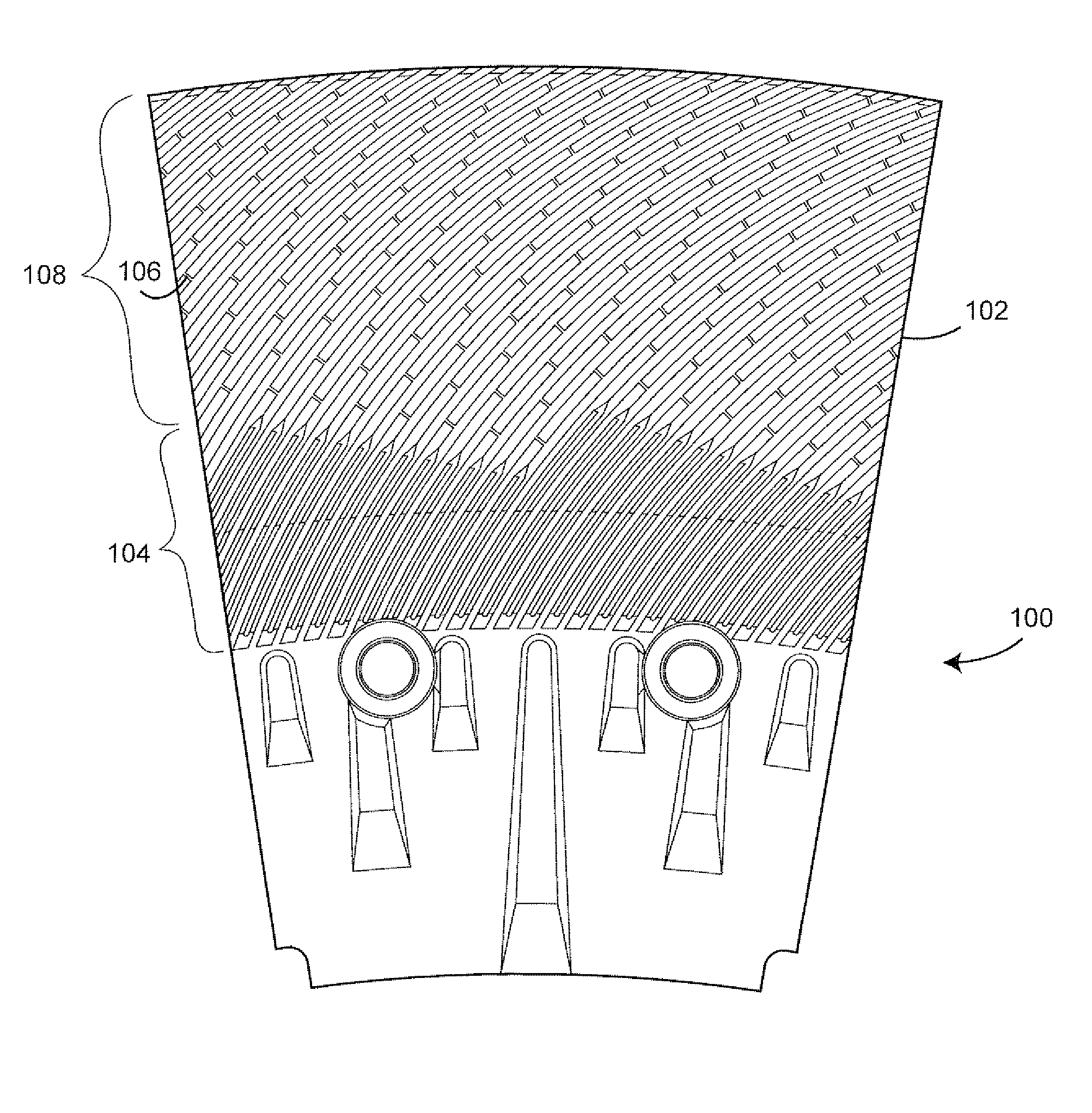
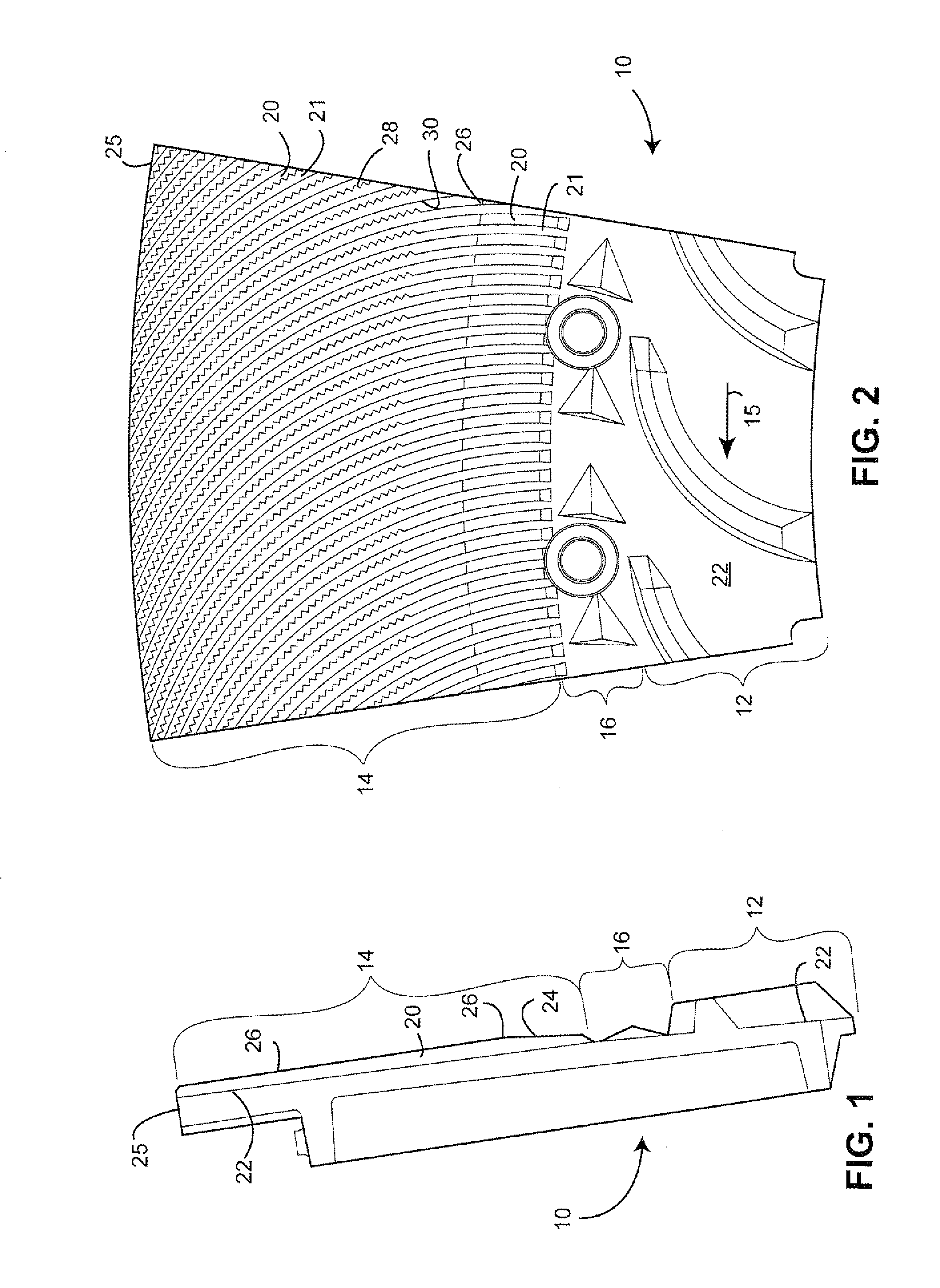
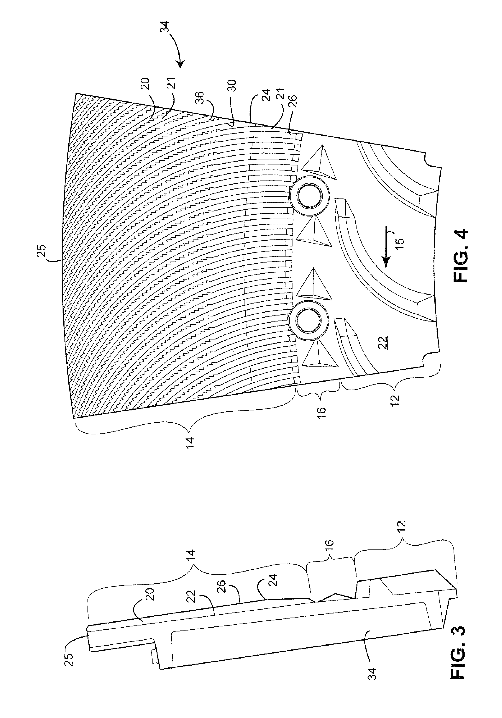
[0039]The mechanical refining process applies cyclical compressions to a fibrous pad of fibrous material moving between opposing refining plates. The compressions result from the rotation of one plate relative to the other and, particularly, to the crossing of bars in the opposing plates. The compressions cause fibers in the material to separate from a network fibers in the material. The plates are typically mounted on discs in a refiner, wherein at least one of the discs rotates one of the refiner plates. The energy efficiency of the refining process may be improved by increasing the compression ratio of the fibrous pad and increasing the period during which fibers in the pad are subjected to the compressions. The increased compression ratios are achieved with the refiner plate designs disclosed herein without necessarily reducing the gap between the plates or reducing the gap only to the extent now done in conventional high energy efficiency refiners.

[0040]A relatively wide gap, e...


PUM

PropertyMeasurementUnit
holdback angleaaaaaaaaaa

Abstract

A refiner plate for a mechanical refiner of lignocellulosic material including: a refining surface on a substrate, wherein the refining surface is adapted to face a refining surface of an opposing refiner plate; wherein the refining surface includes bars and grooves between the bars and the bars have at least a radially outer section in which the bars include a leading sidewall having an irregular surface in the outer section.

Description

CROSS-RELATED APPLICATION[0001]This application claims the benefit of U.S. Provisional Application Ser. No. 60 / 888,817, filed Feb. 8, 2007, the entirety of which is incorporated by reference.BACKGROUND OF THE INVENTION[0002]This invention relates to disc refiners for lignocellulosic materials (referred to as “fibrous material”), and more specifically to disc refiners used for producing mechanical pulp, thermomechanical pulp and a variety of chemi-thermomechanical pulps (collectively referred to as mechanical pulps and mechanical pulping process).[0003]In the mechanical pulping process, raw fibrous material, typically wood or other lignocellulosic material, is fed through the middle of one of a refiners discs and propelled outwards by a strong centrifugal force created by the rotation of one or both discs. The disc(s) typically operate at rotational speeds of 1200 to 2300 revolutions per minute (RPM). While the fibrous material is retained between the discs, energy is transferred to ...

Claims


Application Information

Patent Timeline
Patent Type & Authority Applications(United States)
IPC IPC(8): B02C7/12
CPCD21D1/306
Inventor GINGRAS, LUC
Owner ANDRITZ INC
Why Eureka
Try Eureka