
Regulator with Automatic Power Output Device Detection

Active Publication Date: 2008-08-14
TEXAS INSTR INC
View PDF7 Cites 18 Cited by
  • Summary
  • Abstract
  • Description
  • Claims
  • Application Information

AI Technical Summary

Benefits of technology

[0012]It is a further object of this invention to provide such circuitry and such methods that are operable automatically on power-up, in which the selection state is unconditionally maintained until power-down, thus preventing errors in operation.

Problems solved by technology

However, to the integrated circuit manufacturer, it is inefficient from the standpoint of design and manufacturing resources, as well as from an inventory control and forecasting standpoint, to provide switching regulator integrated circuit devices of separate types for each regulator design, one type having on-chip power MOSFET output driver transistors included in the integrated circuit, and the other type arranged for driving off-chip power MOSFET devices.
This inefficiency becomes especially costly for controller and power management devices that integrate programmable and complex control functions, along with one or more switching regulators, into a single integrated circuit.
However, especially where power dissipation is a concern (as is the case in small form-factor systems such as those mentioned above), it is undesirable to operate the switching regulator to drive on-chip power MOSFET devices when the integrated circuit is in fact being used to drive off-chip power MOSFET devices.
In addition, the switching of the on-chip power MOSFET devices when off-chip power MOSFET devices are being used generates substantial noise in the system, degrading the ability of the switching regulator to maintain a stable output voltage and also generally degrading the operation of the system.
It is also not possible, in some system applications, to programmably control the switching regulator to select one of its two possible outputs.
The use of a jumper or other hard-wired selection technique to make this selection is cumbersome to the system implementer, and in fact may not be available in some applications.

Method used


Image

  • Regulator with Automatic Power Output Device Detection
  • Regulator with Automatic Power Output Device Detection
  • Regulator with Automatic Power Output Device Detection

Examples


Embodiment Construction

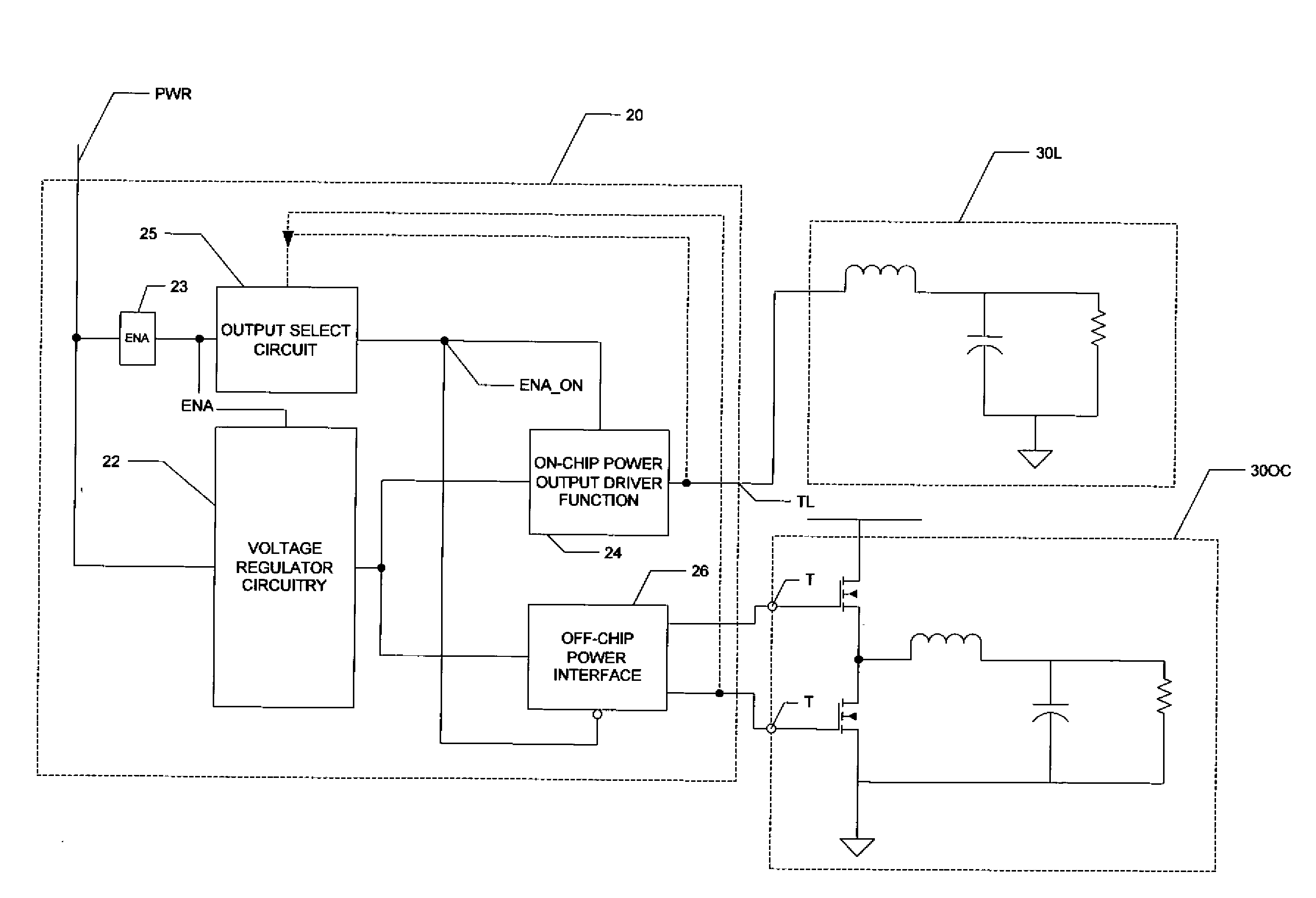
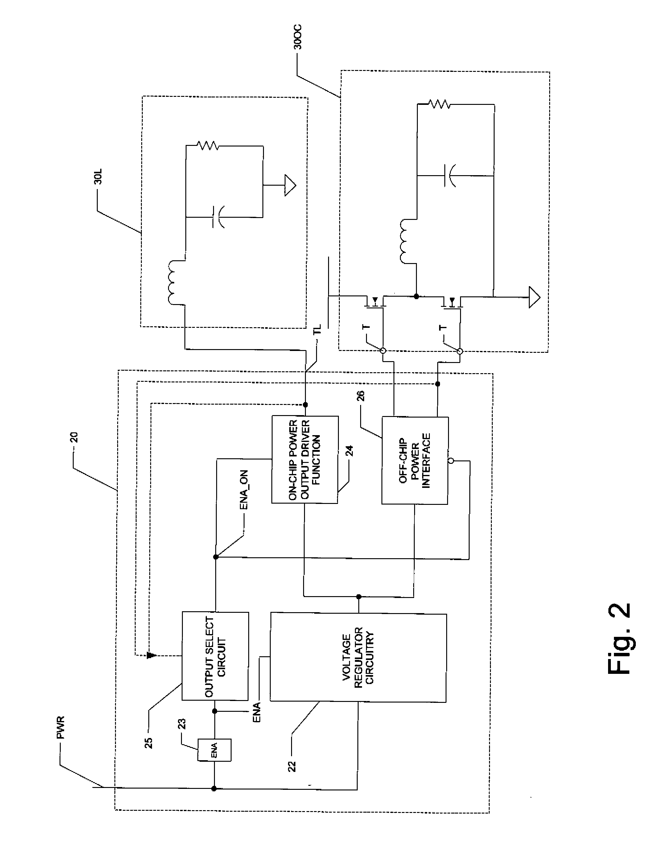
[0021]The present invention will be described in connection with its preferred embodiment, namely as implemented into a switching regulator in a hard disk drive system, because it is contemplated that the invention is especially beneficial to such an application. However, it is contemplated that this invention will be beneficial when used in switching regulators, and indeed any circuits having both on-chip power drive devices and also the capability of using off-chip power drive devices. Accordingly, it is to be understood that the following description is provided by way of example only, and is not intended to limit the true scope of this invention as claimed.

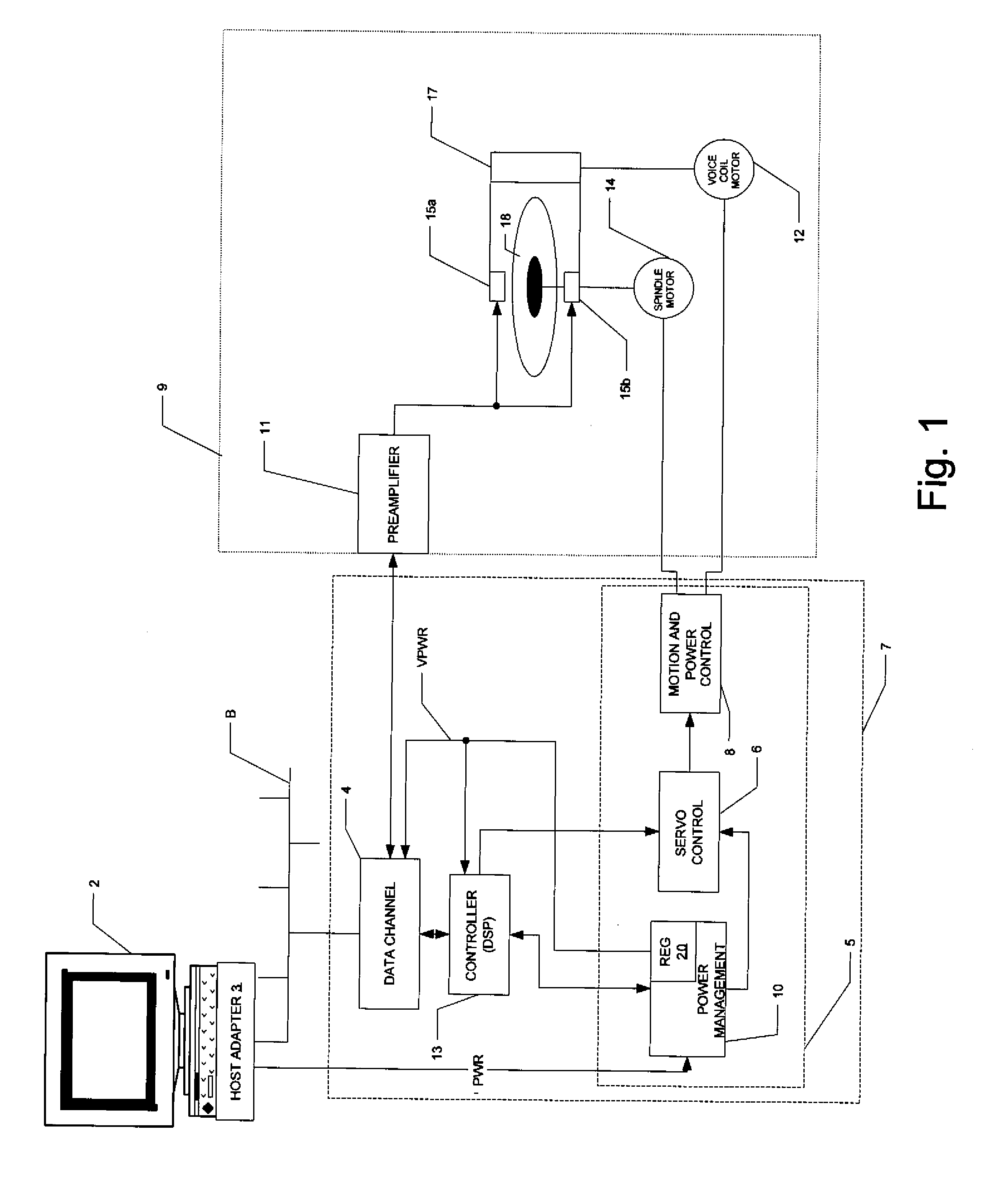
[0022]FIG. 1 illustrates an example of a computer including a disk drive system, into which the preferred embodiment of the invention is implemented. In this example, personal computer or workstation 2 is realized in the conventional manner, including the appropriate central processing unit (CPU), random access memory (RAM), v...


PUM


Abstract

A switching regulator (20) including an on-chip power output function (24) and also an interface (26) to which off-chip power output devices (42PU, 42PD) may be connected is disclosed. The switching regulator (20) includes an output enable circuit (25, 125) that senses the presence of external components at one of the terminals (T_PD, TL) of the on-chip power output function (24) or of the interface (26) to determine which of the output functions to enable. In one disclosed embodiment, the output enable circuit (25) detects whether an off-chip power transistor (T_PD) is connected at the interface (26), by charging a passive circuit (R1, C1) and determining whether the charging time constant is affected by the gate capacitance of the external transistor (42PD). In another disclosed embodiment, the output enable circuit (125) detects whether a load (30L) is connected to the output of the on-chip power output function (24) by measuring the voltage across a resistor (R1), into which a mirrored current is sourced, based on a current applied to the external terminal (TL); if the load (30L) is present, the voltage across the resistor (R1) will cause a logic transition to enable the on-chip power output function (24).

Description

CROSS-REFERENCE TO RELATED APPLICATIONS[0001]Not applicable.STATEMENT REGARDING FEDERALLY SPONSORED RESEARCH OR DEVELOPMENT[0002]Not applicable.BACKGROUND OF THE INVENTION[0003]This invention is in the field of electronic circuits, and is more specifically directed to switching voltage regulators.[0004]As is well known in the electronics art, stable voltage levels are of tremendous importance in many circuit and system applications, particularly those in which the absolute voltage level impacts the accuracy or fidelity of the resulting system. One such system application in which stable voltages are essential is the well-known magnetic disk drive, in which data is written and read to magnetic media. Modem disk drives typically use a servo-controlled “spindle” motor to rotate the disk surfaces under a flying magnetic read-write head, and a servo-controlled “voice-coil” motor to move and control the radial position of the head over the magnetic disk drive surfaces. These motors, and a...

Claims


Application Information

Patent Timeline
IPC IPC(8): G05F1/618G05F1/46
CPCH02M1/36H02M2001/009H02M2001/007H02M3/156H02M1/009H02M1/007
Inventor CHENG, DONGJIEBRITO, JOAO CARLOS
Owner TEXAS INSTR INC
Learn More