Indoor location determination

Inactive Publication Date: 2008-08-14
CORNING MOBILEACCESS
View PDF8 Cites 91 Cited by
  • Summary
  • Abstract
  • Description
  • Claims
  • Application Information

AI Technical Summary

Benefits of technology

[0014]In some embodiments, there is provided a method for determining an indoor location of a transmitter, including the steps of: a) inside an indoor environment, performing an AOA triangulation procedure on the transmitter to provide a tentative indoor transmitter location; and b) using at least one added input to ensure that the tentative transmitter location is an accurate indoor transmitter location. In some embodiments, the step of performing an AOA triangulation includes using at least two direction finders to perform the triangulation, wherein each direction finder includes at least one array of three antennas. In some embodiments, an added input may include measured phase differences

Problems solved by technology

In itself, this processing cannot yield a

Method used


Image

  • Indoor location determination
  • Indoor location determination
  • Indoor location determination

Examples


Embodiment Construction

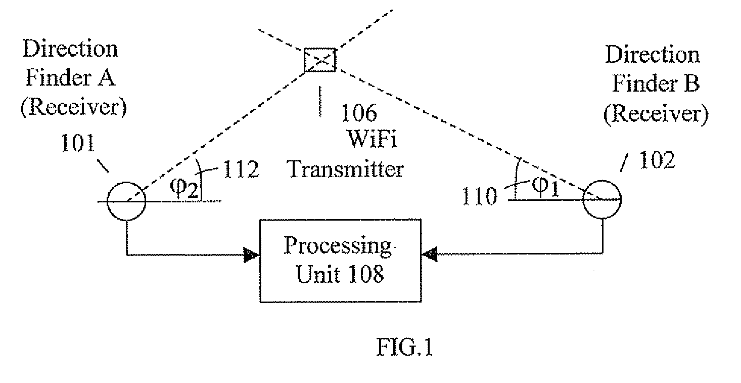
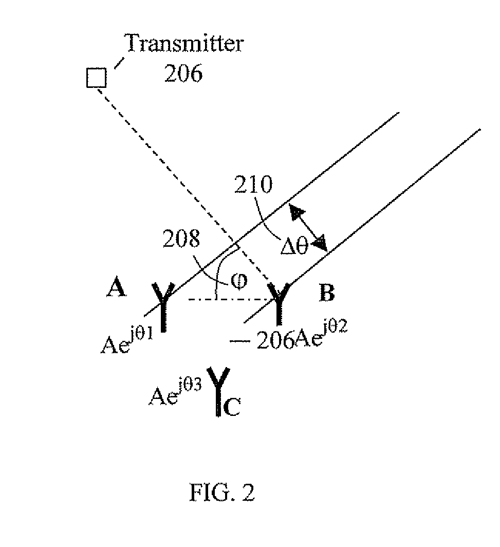
[0026]FIG. 1 shows an embodiment of an indoor location identification system used in the invention. The system includes a first receiver used as direction finder A 101 and a second direction finder B 102, both being antenna arrays of which principle of operation is explained below. Each direction finder includes at least one array of at least three antennas A, B, C (see FIG. 2) and receives from a transmitter 106 a beam (“pointer”) at an angle (p relative to the line between the two receivers. A processing unit 108 coupled to each direction finder receives from each direction finder the respective φ angle. The tentative location of the transmitter can be found based on angles φ1 and φ2 and prior knowledge of the location of the direction finders 101 and 102 (“triangulation”). However, the basic direction finding based on angle of arrival has almost never been applied to indoor environments, and when applied has not been successful, because of the reflections and other artifacts comm...


PUM


Abstract

A tentative location of a transmitter in an indoor environment is determined by triangulation, using at least two direction finders. The tentative location is made more accurate by performing at least one added action selected from the following: checking the likelihood that the tentative location is an accurate location by comparing measured transmitter signal strengths with calculated signal strengths, using a known indoor environment structure, using a record of the transmitter movement through the indoor environment for determining whether the transmitter is located in an obscured area of the indoor environment or performing an alignment procedure on the antennas to improve the triangulation.

Description

CROSS REFERENCE TO RELATED APPLICATIONS[0001]This application claims the benefit of U.S. Provisional Patent Application No. 60 / 889,306 filed Feb. 12, 2007, which is incorporated herein by reference in its entirety.FIELD OF THE INVENTION[0002]The invention relates generally to location identification and more particularly to indoor location identification of devices such as transmitting transmitters or cellular phones or any other hand held devices with ability to transmit radio signals. From now on such devices will be called “transmitters”.BACKGROUND OF THE INVENTION[0003]Location based services for providing services based on location of transmitters are expanding rapidly. Herein, “location” refers to the location of a transmitter described by coordinates or by textual description. “Location determination” refers to the process of determining the location of the transmitter.[0004]Several technologies have been proposed for outdoor location identification, including Time Difference...

Claims


Application Information

Patent Timeline
IPC IPC(8): G01S3/00
CPCG01S3/023G01S5/04G01S5/0252G01S5/02521
Inventor SABAN, OFERSHAPIRA, ISAACHOLTZMAN, YEHUDASHAPIRA, YAIROREN, YAIR
Owner CORNING MOBILEACCESS
Why Eureka
Try Eureka