Light emitting device

a technology of light emitting device and light bulb, which is applied in the direction of lighting and heating apparatus, cooling/ventilation/heating modification, point-like light source, etc., can solve the problems of reducing the life-span of the bulb tube, increasing the heat flux on the surface of the led, and reducing the performance of the light emitting device. , to achieve the effect of reducing the volume of the light emitting device and high heat dissipation ra

Inactive Publication Date: 2008-08-14
COOLER MASTER CO LTD
View PDF2 Cites 81 Cited by
  • Summary
  • Abstract
  • Description
  • Claims
  • Application Information

AI Technical Summary

Benefits of technology

[0010]The advantage of the present invention is that, the heatsink is fixed to the housing to be directly in contact with the light emitting unit inside the housing through the opening without additional heat transfer elements; such that the volume of the light emitting device is reduced while high heat dissipation rate is achieved without the need for multiple heatsinks.
[0011]Further scope of applicability of the present invention will become apparent from the detailed description given hereinafter. However, it should be understood that the detailed description and specific examples, while indicating preferred embodiments of the invention, are given by way of illustration only, since various changes and modifications within the spirit and scope of the invention will become apparent to those skilled in the art from this detailed description.

Problems solved by technology

However, after a light tube or light bulb generally employed is used for a long time, the illumination performance thereof is decayed due to heat generated, thus reducing the life-span of the tube of bulb, so the tube or bulb has to be replaced frequently.
However, a high power LED means the rapid heat generation, and as the LED has a very small volume, the heat flux on the surface of the LED increased significantly.
If the heat generated is not removed in time, the illumination performance of the LED may decay greatly, or the LED may burn out due to over-temperature.
As the heat transfer between the housing and LED is carried out through thermal conduction, and as the contact area between the housing and the LED is rather small due to small volume of the LED, the heat transfer rate of thermal conduction is limited, this cannot meet the requirements of high-power LED.
M278217 is composed of a plurality of heat dissipation bodies, resulting in a light emitting device having a too large volume and requiring increased manufacturing cost.

Method used


Image

  • Light emitting device
  • Light emitting device
  • Light emitting device

Examples


first embodiment

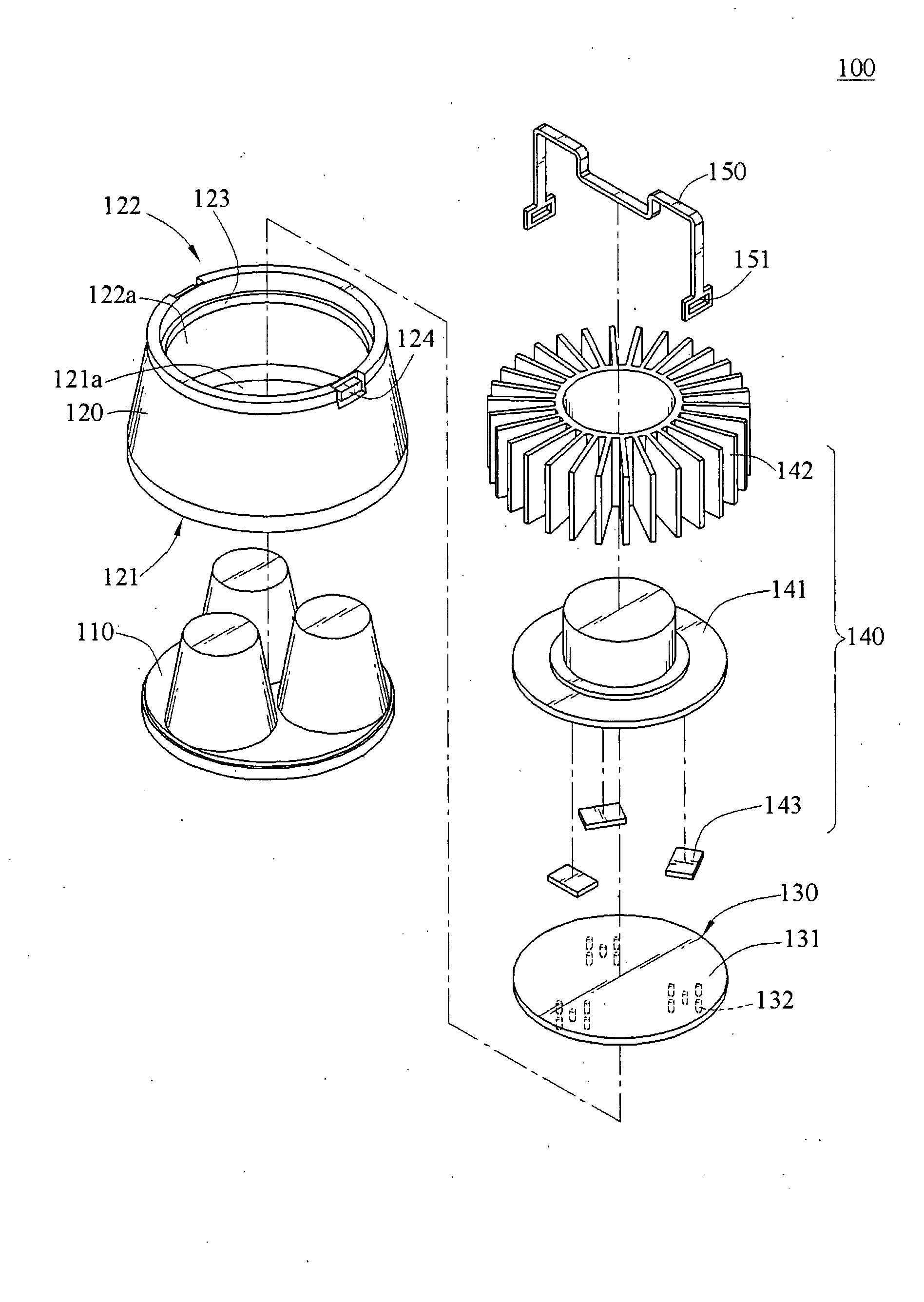
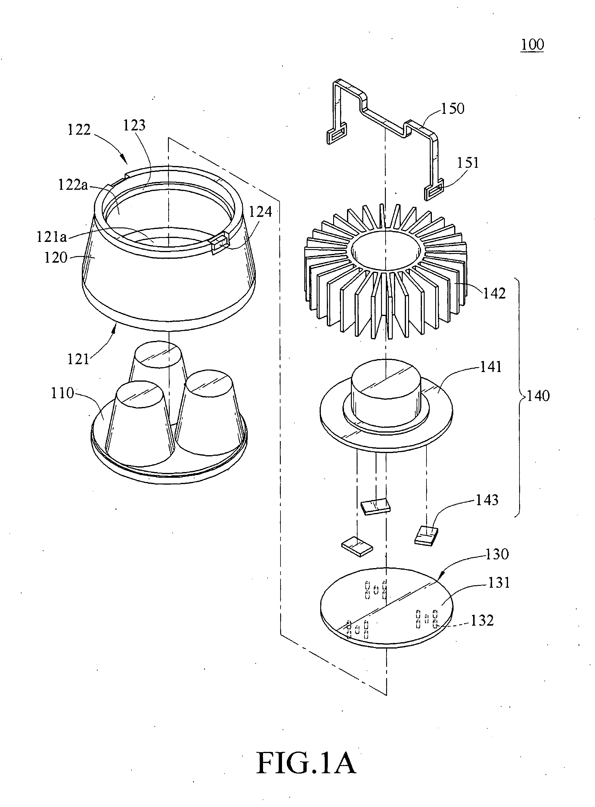
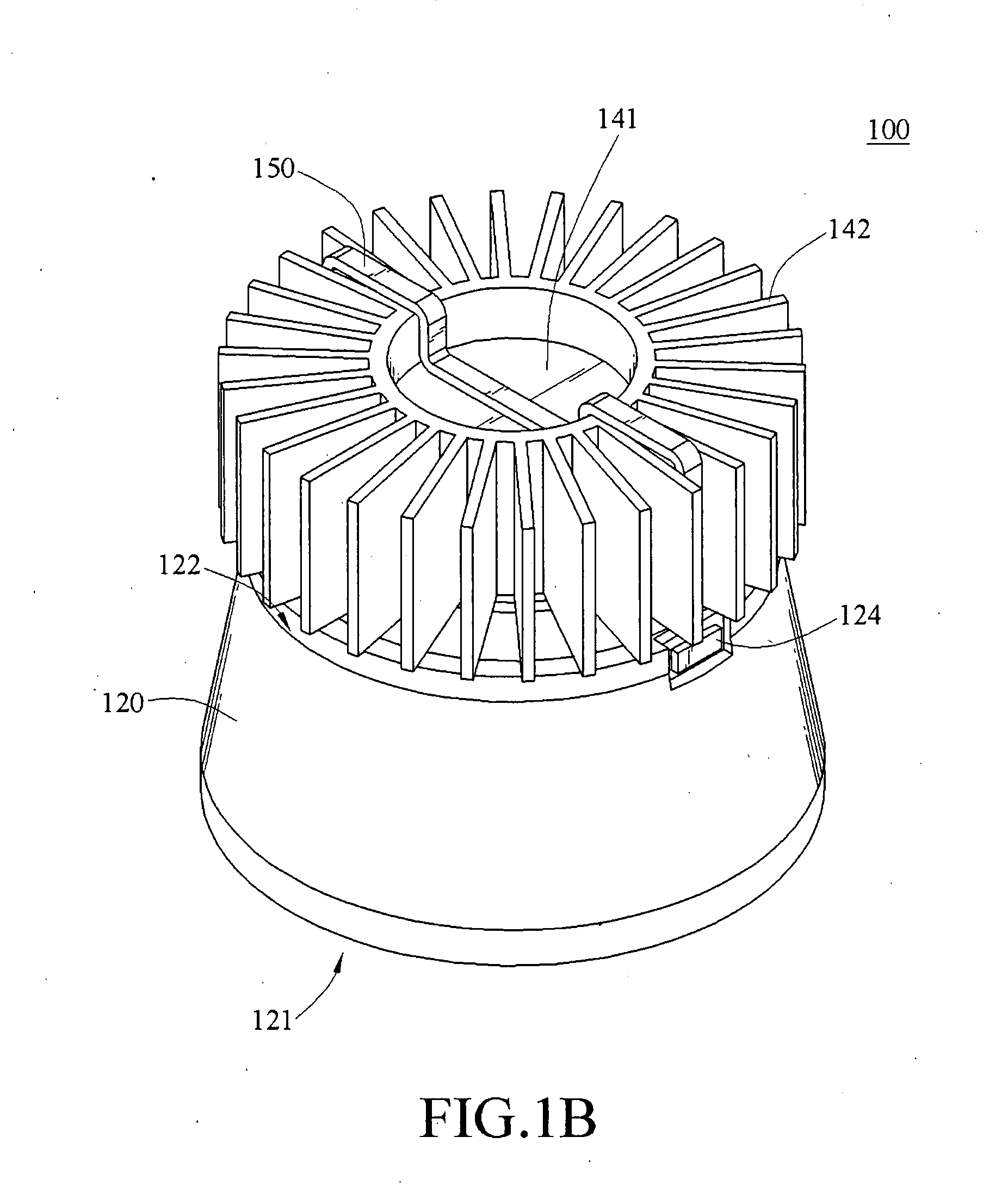
[0035]FIGS. 1A, 1B, and 1C show a light emitting device 100 including a lens assembly 110, a housing 120, a light emitting unit 130, and a heatsink 140 of the present invention.

[0036]Referring to FIGS. 1A, 1B, and 1C, the housing 120 is a hollow structure of any shape, for example, a hollow cone-shaped structure. The housing 120 has a projection end 121 and a heat dissipation end 122 opposite to each other. A first opening 121a is formed in the projection end 121, and a second opening 122a is formed in the heat dissipation end 122. The lens assembly 110 is fixed to the projection end 121 to cover the first opening 121a, so as to install lens assembly 110 to the housing 120.

[0037]Referring to FIGS. 1A, 1B, and 1C, the light emitting unit 130 is disposed inside the housing 120 corresponding to the heat dissipation end 122. The light emitting unit 130 includes a circuit board 131 and one or more light emitting elements 132. The circuit board 131 has an outer diameter similar to that of...


PUM


Abstract

A light emitting device including a housing, a light emitting unit, and a heatsink is provided. The housing has a projection end and a heat dissipation end, and a first opening and a second opening are respectively formed in the projection end and the heat dissipation end. The light emitting unit is disposed inside the housing, and is corresponding to the heat dissipation end, for projecting a light toward the projection end and through the first opening. The heatsink is fixed to the heat dissipation end of the housing, and in contact with one side of the light emitting unit that faces the second opening, for dissipating the heat generated by the light emitting unit to the outside air.

Description

BACKGROUND OF THE INVENTION[0001]1. Field of Invention[0002]The present invention relates to a light emitting device, and more particularly, to a light emitting device with heat dissipation ability.[0003]2. Related Art[0004]Light fixtures seen in daily life, such as traffic lights, lamps, displays of electronic devices, are all assembled with a light emitting element unit to serve as a light source. However, after a light tube or light bulb generally employed is used for a long time, the illumination performance thereof is decayed due to heat generated, thus reducing the life-span of the tube of bulb, so the tube or bulb has to be replaced frequently.[0005]Along with the development in optoelectronics, light emitting diodes (LEDs), which have characteristics of small volume, rapid response, long life-span, and low power consumption, have gradually replaced the conventional light emitting units such as the bulbs, and become the most important light emitting units used widely.[0006]Ho...

Claims


Application Information

Patent Timeline
Patent Type & Authority Applications(United States)
IPC IPC(8): H05K7/20
CPCF21V29/004F21Y2101/02F21V29/773F21V29/763F21V29/75F21Y2115/10F21V29/503
Inventor PENG, CHANG HUNGHUANG, CHUNG CHIN
Owner COOLER MASTER CO LTD
Why Eureka
Try Eureka