Portable Electronic Storage Devices with Hardware Security Based on Advanced Encryption Standard

a technology of encryption standard and electronic storage device, applied in the direction of unauthorized memory use protection, instruments, individual entry/exit registers, etc., can solve the problems of data being compromised, huge security risk for sensitive data, and high cost associated with manufacturing pesd with finger print sensors

Inactive Publication Date: 2008-08-14
SUPER TALENT ELECTRONICS
View PDF3 Cites 61 Cited by
  • Summary
  • Abstract
  • Description
  • Claims
  • Application Information

AI Technical Summary

Benefits of technology

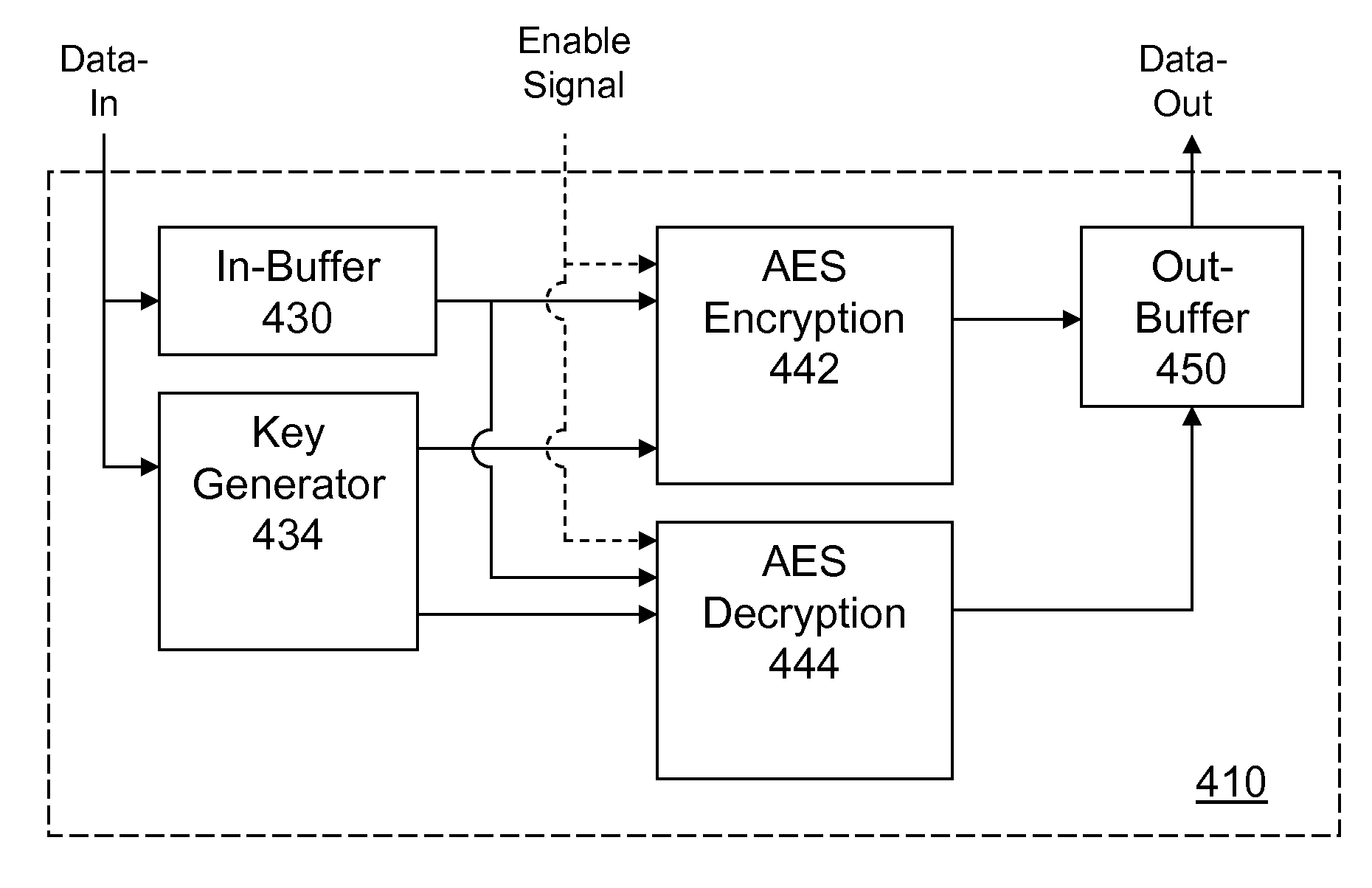
[0018]In yet another aspect, the present invention requires a data encryption / decryption security password to turn on data encryption / decryption. In other words, the security engine may only be activated when a correct encryption / decryption security password has been entered. As a result, a mixed mode of data operation may be implemented. In other words, data stored on a PESD may be encrypted and unencrypted depending upon which mode (encryption / decryption ON or OFF). Because data operations either read or write are in a data file basis, a data file password would provide additional security to those data files have a data file password.

Problems solved by technology

Worse, the data may be compromised even if the owner of the PESD simply misplaces the PESD.
Lack of security on this type of PESD creates a huge security risk for sensitive data (e.g., financial records, personal information, secret data, etc.).
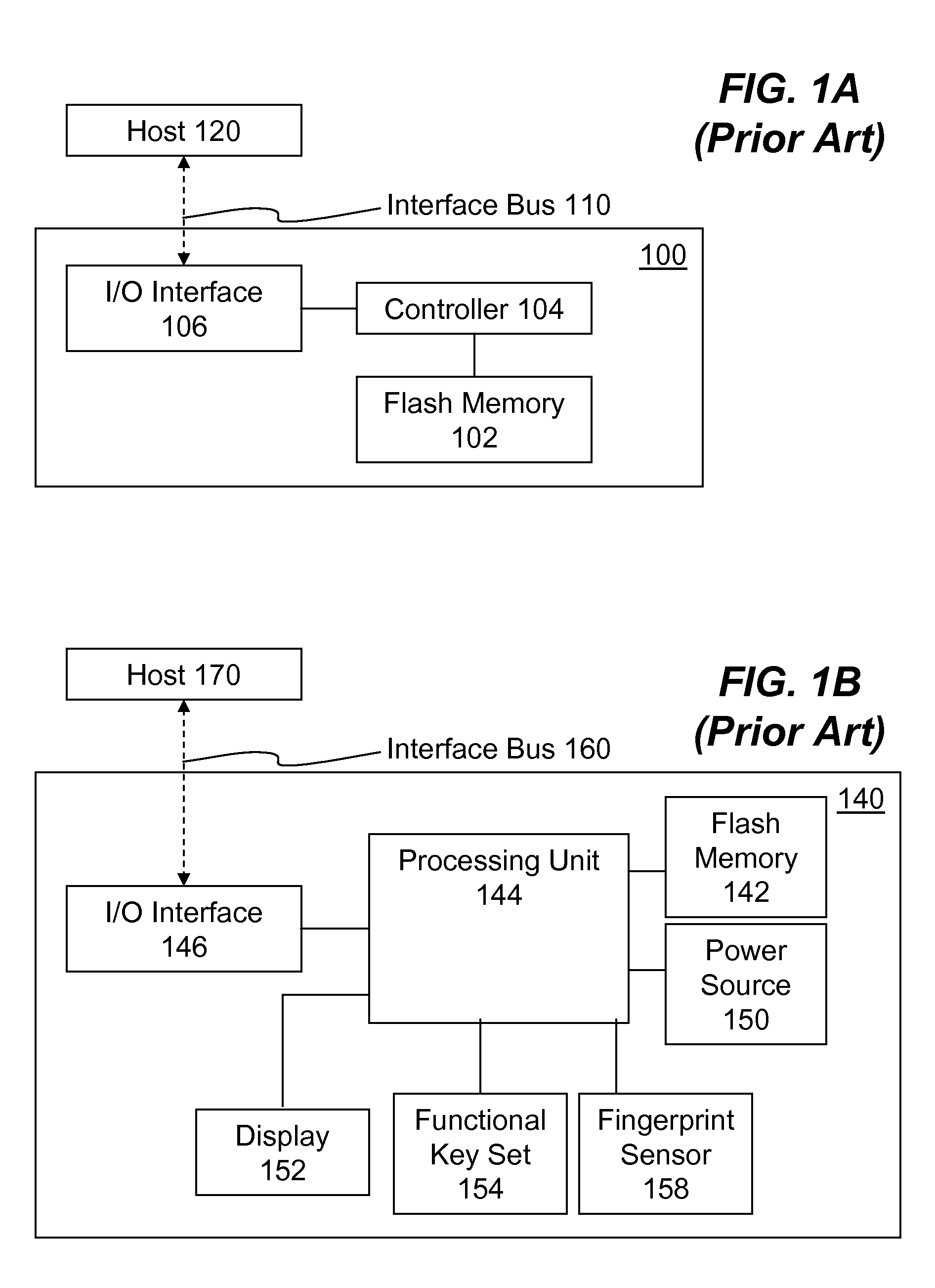
Although the finger print sensor PESD 140 can provide certain level of security to the data stored on the PESD 140, there are problems with this approach.
The drawbacks are as follows: 1) costs associated with manufacturing PESD with finger print sensor are high; 2) complexity related to data sharing when a group of users; 3) finger print sensor may not be reliable as finger print may be altered; and 4) comparison of scan finger print with a reference print may not always be reliable.

Method used


Image

  • Portable Electronic Storage Devices with Hardware Security Based on Advanced Encryption Standard
  • Portable Electronic Storage Devices with Hardware Security Based on Advanced Encryption Standard
  • Portable Electronic Storage Devices with Hardware Security Based on Advanced Encryption Standard

Examples


Embodiment Construction

[0038]In the following description, numerous specific details are set forth in order to provide a thorough understanding of the present invention. However, it will become obvious to those skilled in the art that the present invention may be practiced without these specific details. The descriptions and representations herein are the common means used by those experienced or skilled in the art to most effectively convey the substance of their work to others skilled in the art. In other instances, well-known methods, procedures, components, and circuitry have not been described in detail to avoid unnecessarily obscuring aspects of the present invention.

[0039]Reference herein to “one embodiment” or “an embodiment” means that a particular feature, structure, or characteristic described in connection with the embodiment can be included in at least one embodiment of the invention. The appearances of the phrase “in one embodiment” in various places in the specification are not necessarily ...


PUM


Abstract

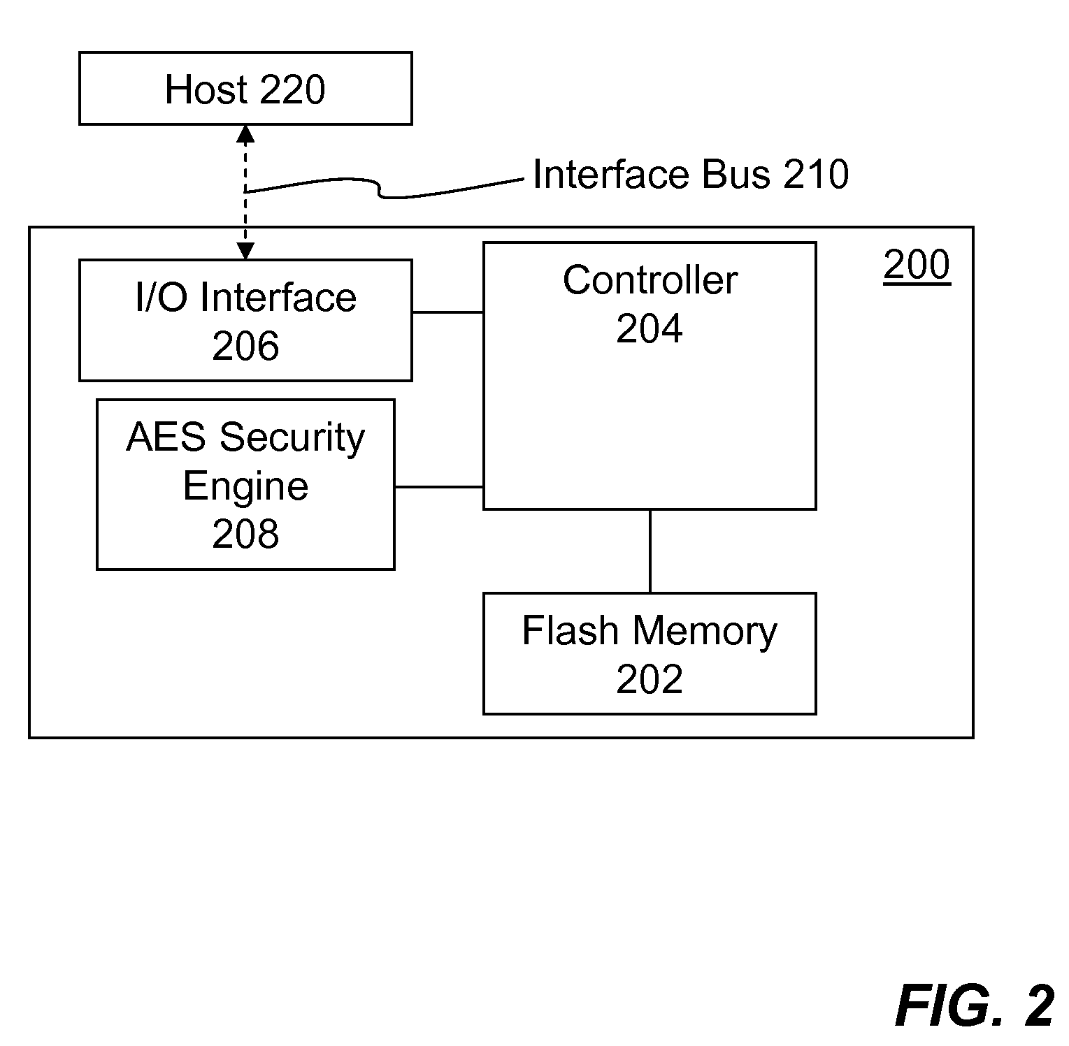
Portable electronic storage devices with hardware based security are described. According to one exemplary embodiment of the present invention, a portable electronic storage device (PESD) comprises a security engine integrated thereon. The security engine is configured to provide data encryption, data decryption, and encryption / decryption key (referred to as a key) generation according to a security standard (e.g., Advance Encryption Standard (AES)). AES is a symmetric encryption algorithm processing data in block of 128 bits. Under the influence of a key, a 128-bit data block is encrypted by transforming the data block in a unique way into a new data block of the same size. AES is symmetric sine the same key is used for encryption and the reverse transformation (i.e., decryption). The only secret necessary to keep for security is the key. AES may use different key-lengths (i.e., 128-bit, 192-bits and 256-bits).

Description

CROSS-REFERENCE TO RELATED APPLICATIONS[0001]This application is a continuation-in-part (CIP) of co-pending U.S. patent application Ser. No. 11 / 624,667 filed on Jan. 18, 2007, entitled “Electronic data Storage Medium with Fingerprint Verification Capability”, which is a divisional patent application of U.S. patent application Ser. No. 09 / 478,720 filed on Jan. 6, 2000, now U.S. Pat. No. 7,257,714.[0002]This application is also a CIP of co-pending U.S. patent application Ser. No. 11 / 674,645 filed on Feb. 13, 2007, entitled “Recycling Partially-Stale Flash Blocks Using a sliding Window for Multi-Level-Cell (MLC) Flash Memory”, which is a CIP of co-pending U.S. patent application Ser. No. 11 / 466,759 filed on Aug. 23, 2006, entitled “Flash Memory Controller for Electronic Data Flash Card”, which is a CIP of U.S. patent application Ser. No. 10 / 789,333 filed on Feb. 26, 2004 entitled “System and Method for Controlling Flash Memory”.[0003]This application is also a CIP of co-pending U.S. pa...

Claims


Application Information

Patent Timeline
Patent Type & Authority Applications(United States)
IPC IPC(8): H04L9/28H04L9/00G06F12/14
CPCG06F12/1416G06F21/78G06F21/85G06F2221/2107G06K19/07H04L9/0631G07C9/00087H04L9/3228H04L9/0894H04L2209/34G06K19/07354G07C9/257
Inventor YU, I-KANGCHOW, DAVID Q.LEE, CHARLES C.MA, ABRAHAM CHIH-KANGSHEN, MING-SHIANG
Owner SUPER TALENT ELECTRONICS
Why Eureka
Try Eureka