Power Control Method for Base Station

a power control and wireless technology, applied in power management, antennas, electrically long antennas, etc., can solve the problems of large power waste, limited system capacity, increased interference, etc., and achieve the effect of reducing the power difference between different signals, improving system capacity, and ensuring the quality of system communication

Active Publication Date: 2008-08-14
SHANGHAI ULTIMATE POWER COMM TECH
View PDF3 Cites 12 Cited by
  • Summary
  • Abstract
  • Description
  • Claims
  • Application Information

AI Technical Summary

Benefits of technology

[0025]In the present invention, when the base station adjusts the corresponding signal transmit power with a step size designated by the higher layer or predefined according to the received power control command of the terminal, the transmit power of the code-channel occupied by the terminal is calculated. Then, the adjusted signal transmit power is corrected according to the transmit power of all the code-channels occupying the same carrier frequency and the same time slot, and the power difference between the code-channels are limited in a range predefined or designated by the higher layer, so that problems in a CDMA system, such as the power difference between code-channels is too large with the downlink power control technology, may be solved.
[0026]The decrease of the power difference between different signals is also favourable to demodulate a signal with low power, thus the quality of system communication may be guaranteed, and the possibility of wireless link out-of-synchronization and even off-line may be lowered. In the present invention, because the object to be adjusted has a low power, other users may not be affected greatly when the signal transmit power is raised appropriately, and the present invention is favourable to improve the system capacity.
[0027]Therefore, by the present invention, the signal power difference between different users may be controlled, the stability of the wireless link may be improved, and the quality of system communication may be guaranteed.

Problems solved by technology

A CDMA (Code Division Multiple Access) system is a self-interfering system, wherein a transmit power of a mobile station is an interference to other users occupying the same frequency in the cell, and a Near-Far Effect is a predominant problem.
However, the transmit power of the base station must be configured according to the coverage area or the terminal farthest from the base station, thus great power will be wasted, the inter-system interference will be increased, and the system capacity will be limited.
If the difference between the transmit powers is too great, a signal with low power may be submerged in a signal with high power at any moment, and the stability of the wireless link will be influenced, thus the quality of communication may not be guaranteed.
However, it is difficult to be implemented in practice.
In the prior system, it usually employs a suboptimal joint detection algorithm or a joint detection algorithm simplified according to a certain model hypothesis, thus, the ability to overcome Near-Far Effect is limited.
Too large power difference will degrade the demodulation performance.
However, because the transmit power difference between different signals is not considered, the signal power difference may be too large.
When the difference exceeds a certain range, a signal with lower power will be submerged in a signal with higher power and thus be interfered.
Therefore, the required signal may not be demodulated correctly, the quality of communication will be degraded, and even the out-of-synchronization or off-line may be caused.
When the terminal uses the joint detection algorithm, the detection of the signal with low power may not be accurate, so that the detection and demodulation of the signal with high power may also be influenced, and the quality of the communication may be degraded.

Method used


Image

  • Power Control Method for Base Station
  • Power Control Method for Base Station
  • Power Control Method for Base Station

Examples


Embodiment Construction

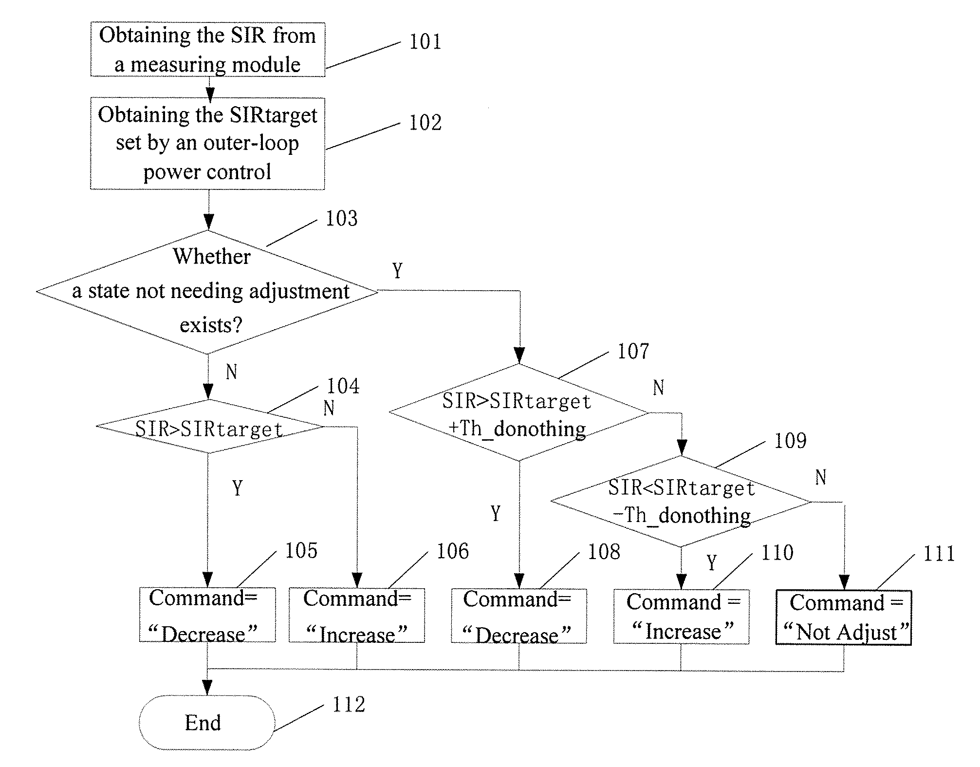
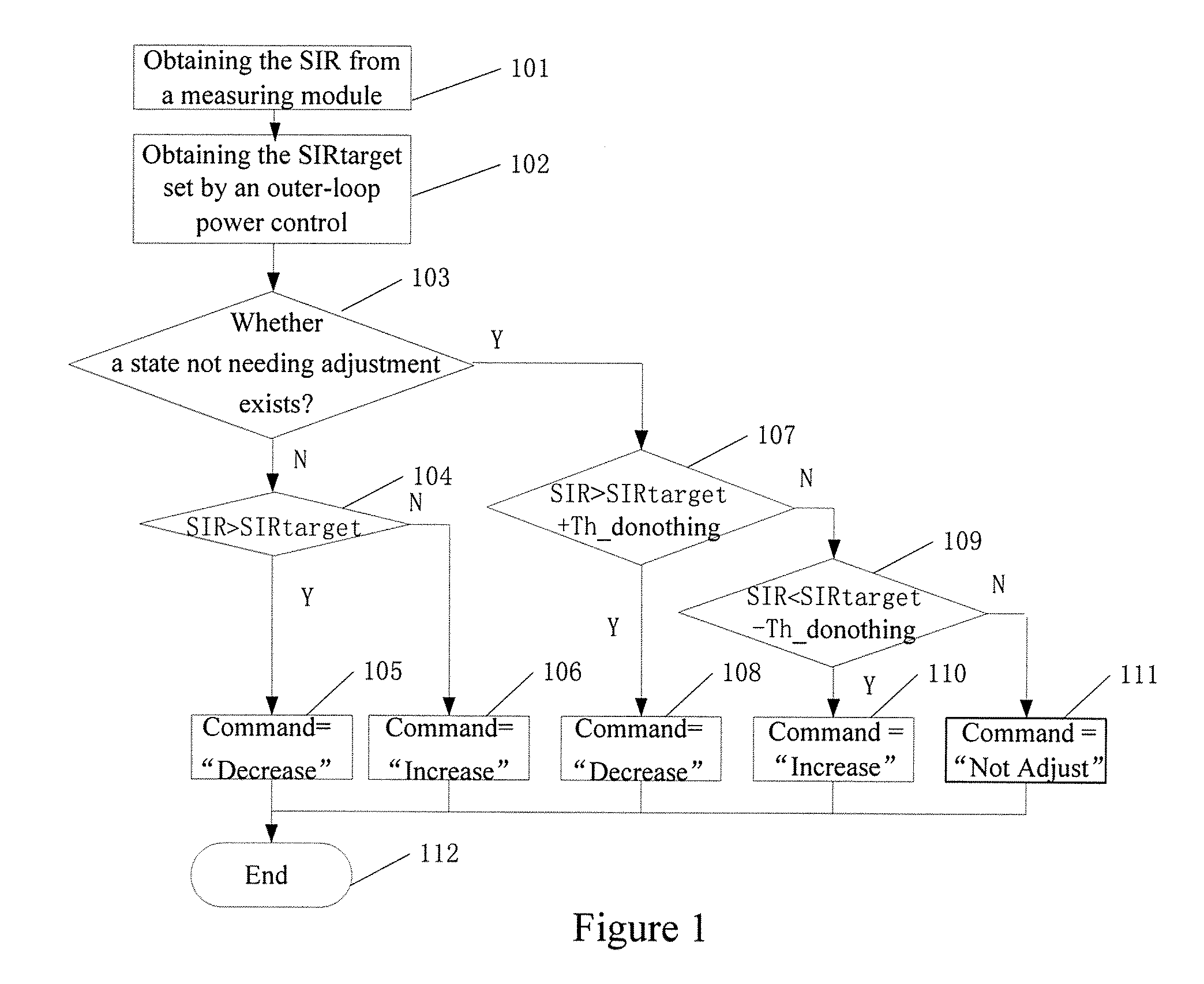
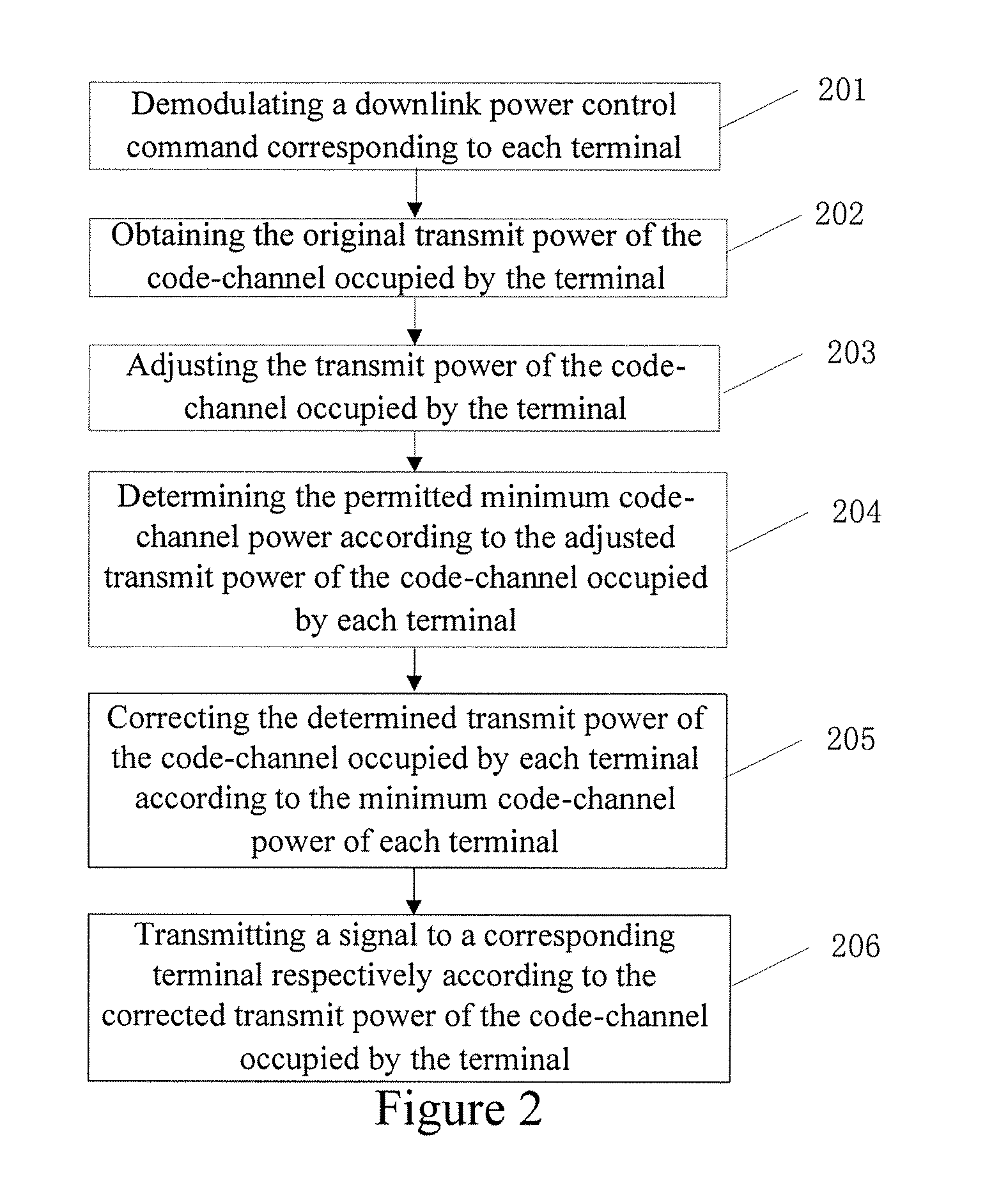
[0031]The concept of the present invention is as follow: when a base station adjusts a signal transmit power with a designated or predefined step size according to a received power control command of the terminal, the transmit power of the code-channel occupied by each terminal is calculated; then, the minimum code-channel power permitted by all code-channels in current carrier frequency and current time slot is determined according to the maximum code-channel power in the code-channels occupying the carrier frequency and the time slot; and then the signal transmit powers corresponding to all the code-channels in the current carrier frequency and the current time slot, which are adjusted according to the power control command, are corrected according to the minimum code-channel power; in all the code-channels of the current carrier frequency and the current time slot, if a power of a code-channel is lower than the permitted minimum code-channel power, the power will be corrected as ...


PUM


Abstract

A downlink power control method for base station, includes following steps: according to the received power control command, base station obtains the transmission power of each terminal occupying code channel; according to the transmission power of each terminal occupying code channel, determines the allowable minimum code channel power of each terminal; according to the determined minimum code channel power of each terminal, amends the transmission power of each terminal occupying code channel; according to the amended transmission power of each terminal occupying code channel, sends signals to the corresponding terminal respectively. Present invention could control the difference of signal power between different users, increase the stability of wireless link, and assure the quality of system communication.

Description

FIELD OF THE INVENTION[0001]The present invention relates to the field of mobile communications, in particular, to a power control method for a wireless base station.BACKGROUND OF THE INVENTION[0002]A CDMA (Code Division Multiple Access) system is a self-interfering system, wherein a transmit power of a mobile station is an interference to other users occupying the same frequency in the cell, and a Near-Far Effect is a predominant problem. The so called Near-Far Effect refers to that, when mobile phones with different distances from the base station are used simultaneously, a signal with a higher power and nearer to the base station will suppress a signal with a lower power and farther from the base station. Therefore, it is expected to make the transmit power of each mobile station maintain a minimum level to meet the requirement for communication as far as possible, and to make the mobile station obtain a basically same power on the base station side regardless of the distance fro...

Claims


Application Information

Patent Timeline
Patent Type & Authority Applications(United States)
IPC IPC(8): H04B7/00
CPCH04W52/346
Inventor SUN, JIANXUNXU, TIEZHU
Owner SHANGHAI ULTIMATE POWER COMM TECH
Why Eureka
Try Eureka