
Implement for orientating a tool, particularly useful in surgical tools for harvesting and implanting bone plugs to repair damaged bone tissue

a technology of orientation and tools, which is applied in the field of orientation tools, can solve the problems of reducing causing pain and swelling, and generally not including the means to establish the perpendicularity of the harvested plug, so as to and reduce the hazard of cartilage separation or damage. , the effect of little for

Active Publication Date: 2008-08-14
DEPUY MITEK INC
View PDF22 Cites 43 Cited by
  • Summary
  • Abstract
  • Description
  • Claims
  • Application Information

AI Technical Summary

Benefits of technology

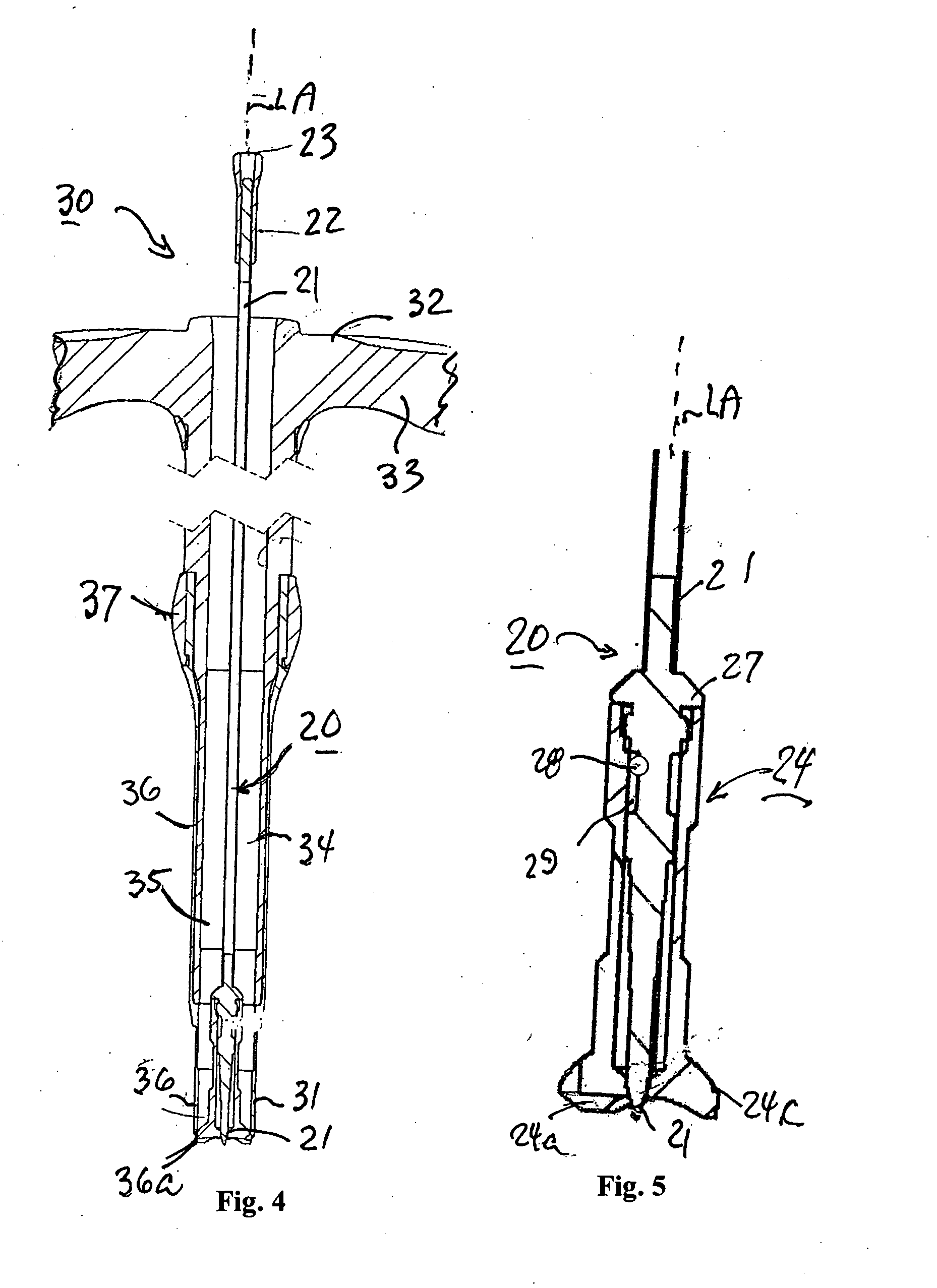
[0016]As will be described more particularly below, an implement for orientating a—tool particularly a surgical tool, constructed in accordance with the foregoing features enables the surgical tool to be precisely oriented at the desired angle (usually perpendicularly) with respect to the target surface to be engaged by the tool, even though the view of the target surface is very limited or obstructed.
[0018]As will be described below, such a method has a number of advantages over existing methods, in that it eliminates the need to transfer the bone plug from the harvester device into a separate delivery device, or to apply a separate delivery device to the harvester device. Moreover, as the harvested bone plug lies distal to the integral delivery section of the harvesting device, the plug is transferred into the delivery section cartilage layer first, i.e. opposite to the direction of transfer in predicate devices, thereby reducing the hazard of cartilage separation or damage. In addition, the transparent section of the tubular cutting tool, since it is used only for temporarily retaining the plug until the tool is transferred to the recipient site, may be of slightly larger diameter than the cutting section formed with the sharp cutting edge, such that relatively little force is needed for transferring the plug from the transparent section to the bore at the recipient site, thereby further reducing the hazard of cartilage separation or damage.

Problems solved by technology

A defect in, or damage to, the cartilage will cause local irritation, producing pain and swelling.
However, they generally do not include means to establish perpendicularity of the harvested plug, but rather rely on visual estimation only.
In procedures performed arthroscopically, the narrow field of vision makes visual assessment difficult and not sufficiently accurate for this purpose.
Another drawback of most available devices and systems is that they require the transfer from the harvester into a separate delivery device, or require the application of a delivery sheath over the harvester tube (e.g., see for example the above-cited U.S. Pat. No. 6,767,354).
Transferring the graft from one tube to another presents a serious hazard to graft integrity as it can lead to the separation of the cartilage layer from the bone plug.
Transferring the graft from the harvester tube via a delivery sheath, as in U.S. Pat. No. 6,767,354, is generally done by mallet blows on the proximal face of the plug, and therefore also involves a grave hazard of separation of the cartilage from the bone because of the friction between the plug and the wall of the delivery sheath.

Method used


Image

  • Implement for orientating a tool, particularly useful in surgical tools for harvesting and implanting bone plugs to repair damaged bone tissue
  • Implement for orientating a tool, particularly useful in surgical tools for harvesting and implanting bone plugs to repair damaged bone tissue
  • Implement for orientating a tool, particularly useful in surgical tools for harvesting and implanting bone plugs to repair damaged bone tissue

Examples


Embodiment Construction

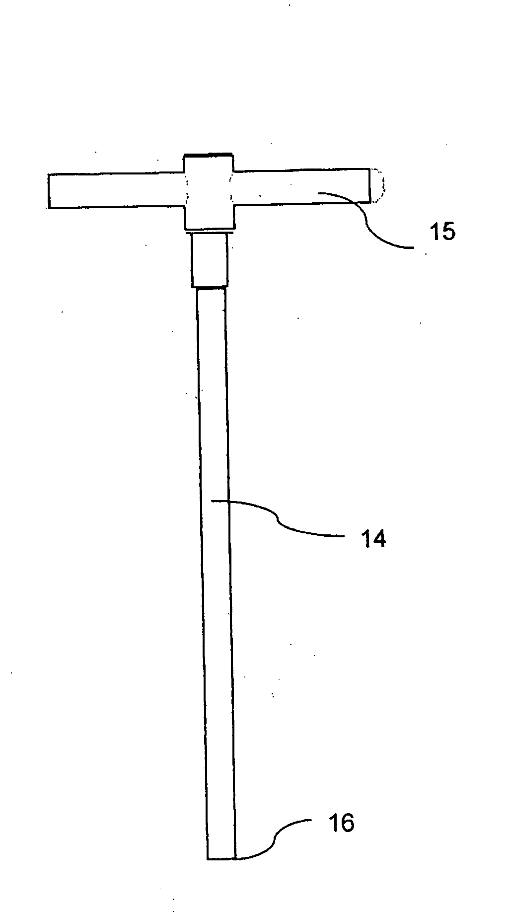
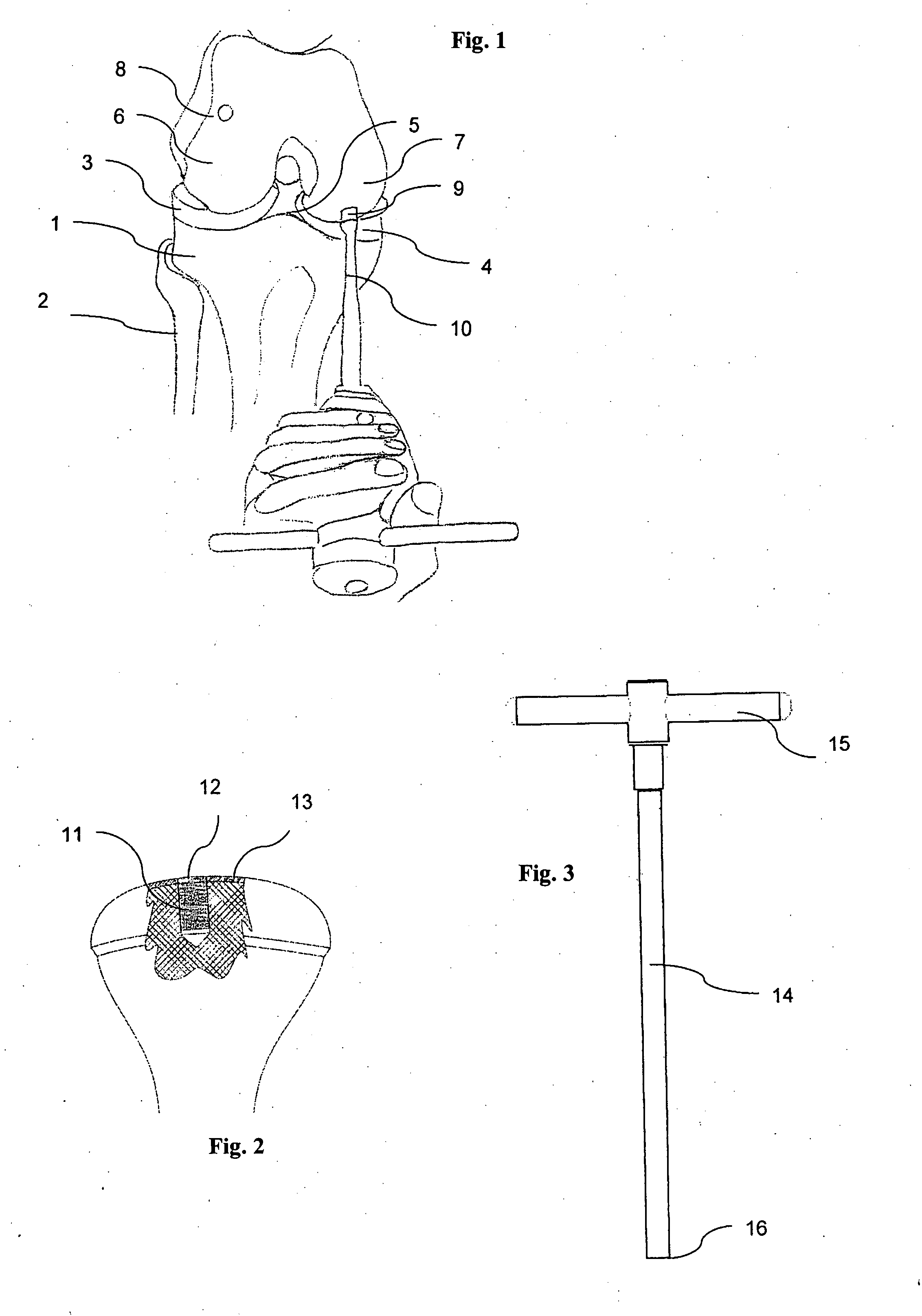
[0031]The Overall Osteochrondal Graft Procedure (FIGS. 1-3)

[0032]For purposes of example, the preferred embodiment of the invention described below is an osteochrondral graft procedure. Such a procedure involves the treatment of a cartilage lesion in a patient's knee in order to repair damaged bone tissue at a donor site therein by harvesting a bone plug from healthy bone tissue at a donor site in a non-load-bearing joint surface in the patient's body, and implanting the bone plug in a bore formed in the damaged bone tissue at the recipient site of the patient's body. The procedure includes the following main steps:

[0033]1. Opening portals for visualization, irrigation and accommodation of the instrument;

[0034]2. Assessing the area of the lesion and determining the number and size of bone grafts (bone plugs) needed to cover the entire damaged area, starting adjacent to healthy bone;

[0035]3. Harvesting from the donor site a perpendicular bone plug suitable for implantation;

[0036]4. D...


PUM


Abstract

An implement for orientating a tool at a predetermined angle with respect to a plane of a target surface to be engaged by the tool includes a rod having a distal end coupled to a head formed with three contact points arranged in a circular array around the longitudinal axis of the rod, such that the three contact points define a plane. The rod is coupled to the head with the longitudinal axis of the rod at the predetermined angle to the plane defined by the three contact points, such that when the three contact points of the rod are in contact with the target surface, the longitudinal axis of the rod is at the predetermined angle with respect to the plane of the target surface. The implement is described particularly for orientating a surgical cutting tool perpendicularly to bone tissue for harvesting and implanting a bone plug to repair damaged bone tissue.

Description

FIELD AND BACKGROUND OF THE INVENTION[0001]The present invention relates to an implement for orientating a tool at a predetermined angle with respect to a target surface to be engaged by the tool. The invention is particularly useful in surgical tools for harvesting and implanting bone plugs to repair damaged bone tissue, and is therefore described below with respect to such an application, but it will be appreciated the invention can be used in other applications. The invention also relates to a method of harvesting and implanting bone plugs to repair damaged bone tissue.[0002]The surfaces of the bones in a sinovial joint, such as the knee, have protective covers made up of articular cartilage. The cartilage optimizes weight distribution over the joint surface, minimizes friction and wear, and allows for a smooth glide over the joint surface with motion. Beneath this protective cover of articular cartilage lies a layer of subchondral bone, followed by cancellous bone.[0003]A defect...

Claims


Application Information

Patent Timeline
Patent Type & Authority Applications(United States)
IPC IPC(8): A61B17/56B25B33/00
CPCA61B17/1604A61B17/1635A61B17/1675A61B2017/00969A61F2002/4687A61F2/4601A61F2/4618A61F2002/4627A61B17/1764
Inventor OREN, RANBARBER, ALAN F.FUERST, YARONMOOR, DAN
Owner DEPUY MITEK INC
Learn More