Communication Control Apparatus
- Summary
- Abstract
- Description
- Claims
- Application Information
AI Technical Summary
Benefits of technology
Problems solved by technology
Method used
Image

Examples
first embodiment
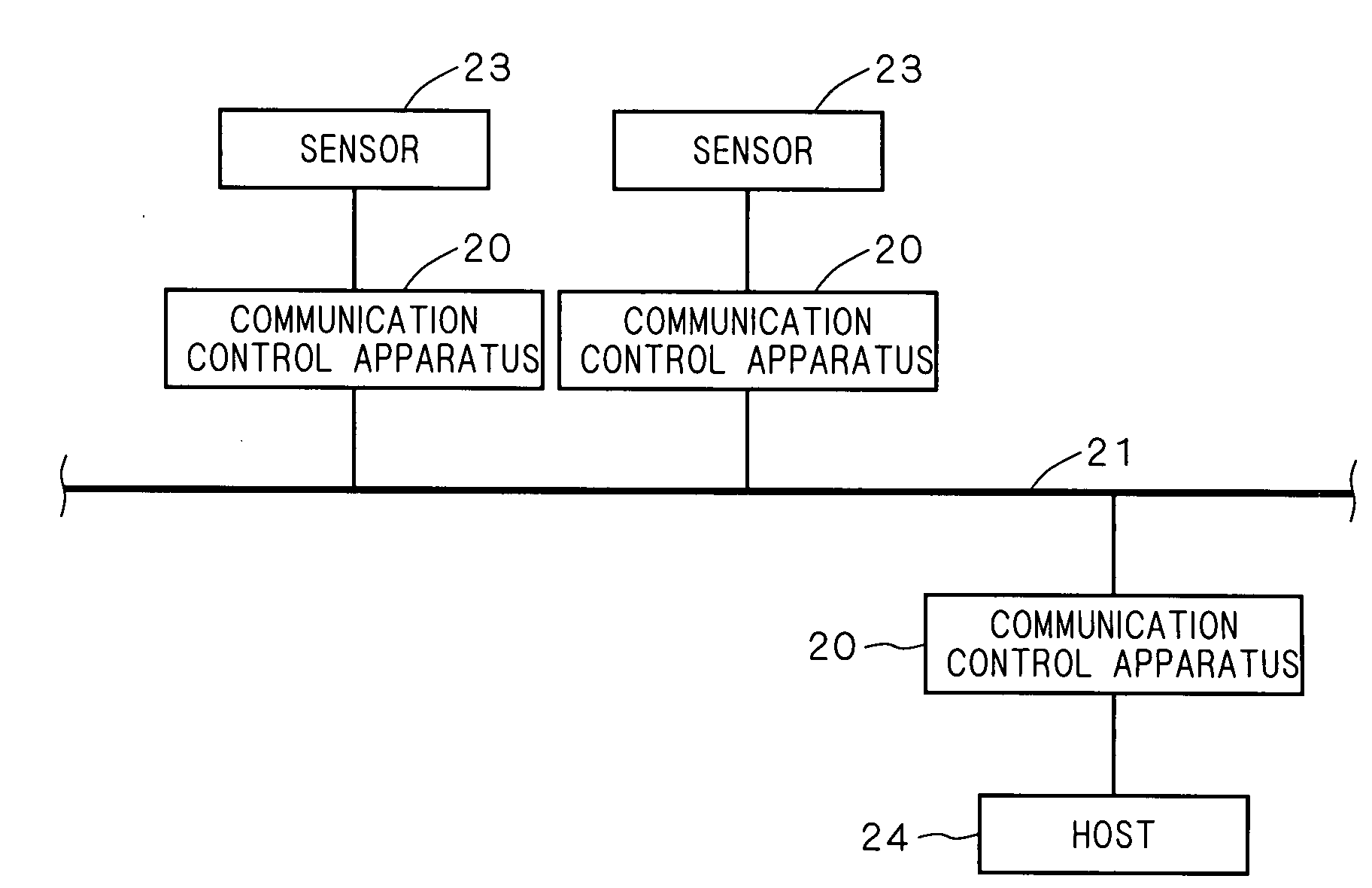
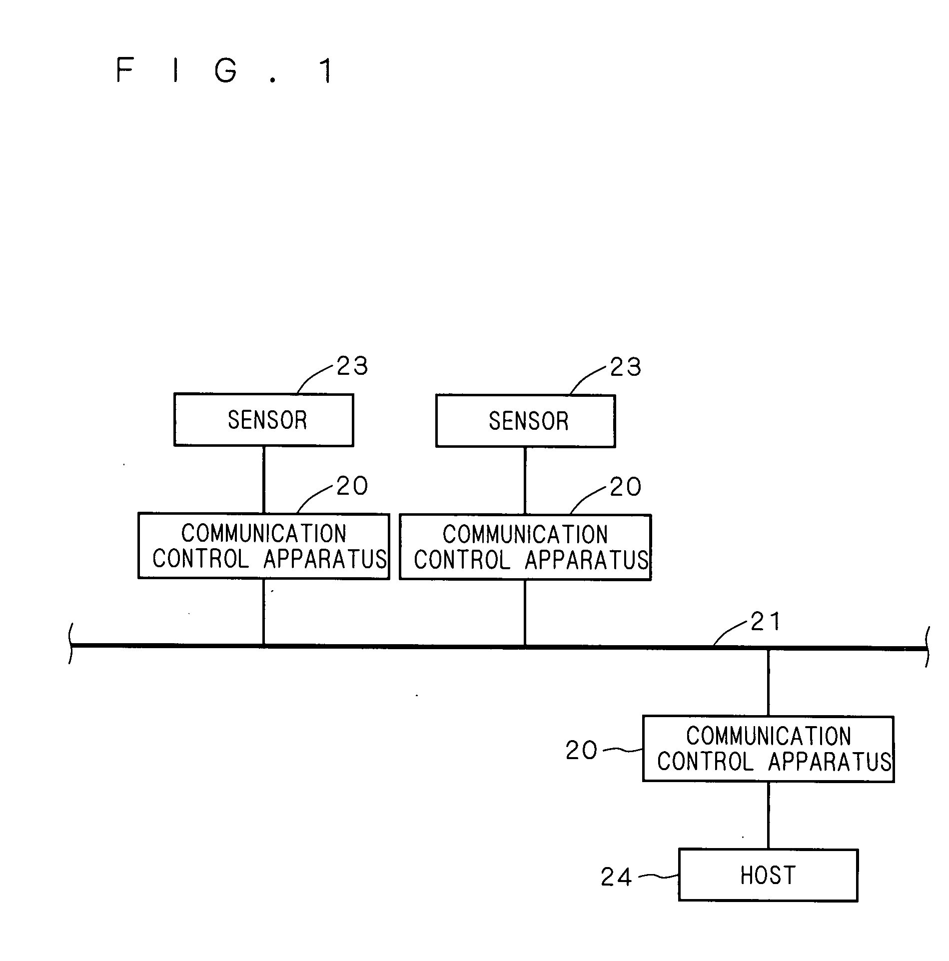
[0034]FIG. 1 is a block diagram showing the outline of the vehicle installed network system constructed using a communication control apparatus 20 according to the embodiment of the present invention. In FIG. 1, a communication driver 25 described later is not shown.
[0035]In this vehicle installed network system, a plurality of communication control apparatuses 20 are connected to a network 21 and the distributed positions in a vehicle are measured with a plurality of sensors 23. A measurement result thereof is collected by a host 24 which is a computer unit, for example, micro computer. Communication is carried out with the communication control apparatus 20 through the network 21 between each sensor 23 and the host 24. This communication control apparatus 20 is capable of broadcasting and functions as a node on the network achieved according to a communication system which transmission right is given regularly.
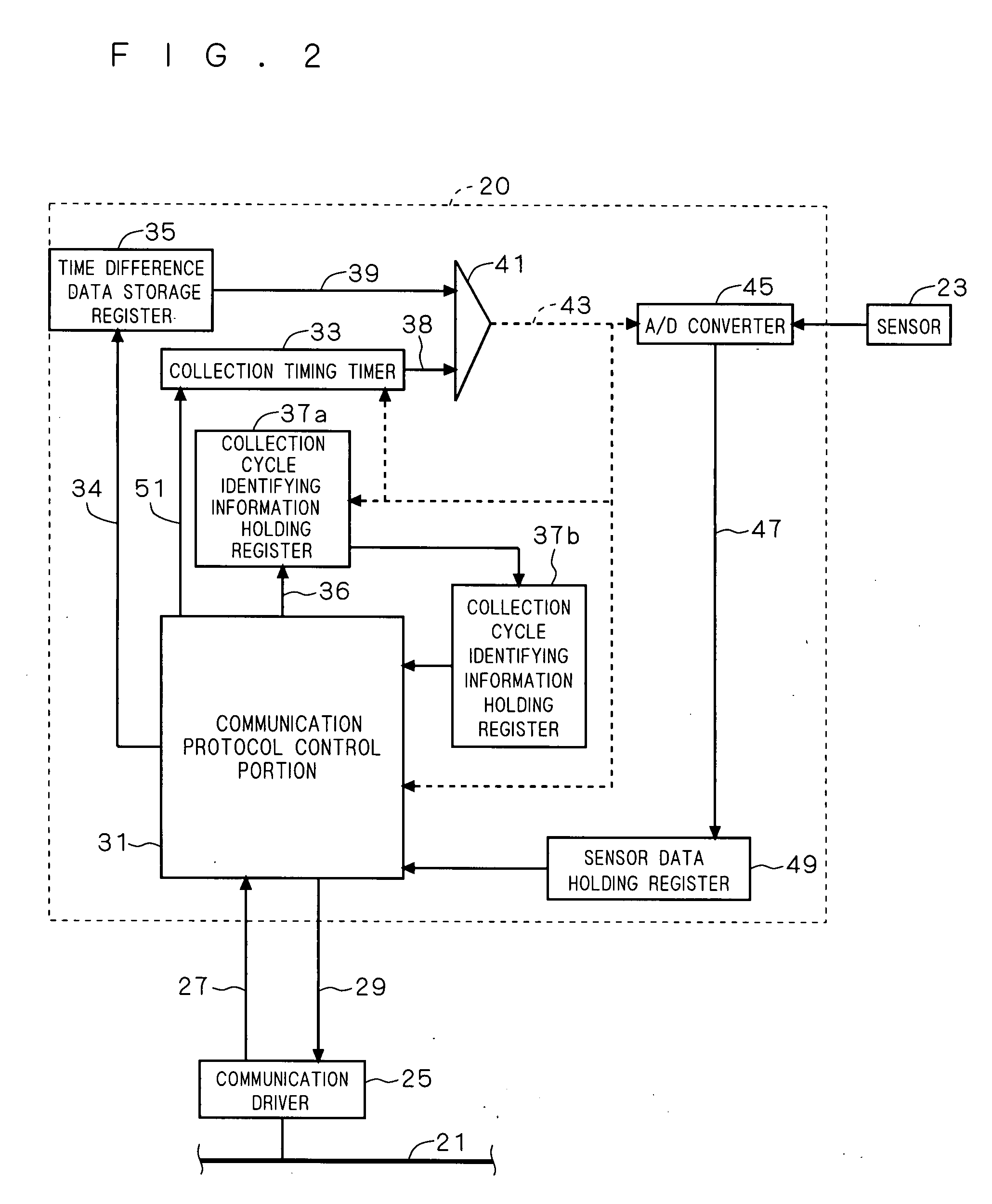
[0036]FIG. 2 is a block diagram showing the communication control appar...
example 1
[0091]A specific example (example 1) of the communication control apparatus 20 of this embodiment will be described. FIG. 7 is a block diagram showing a leakage preventing circuit in a vehicle using the communication control apparatus 20 of the example 1. In FIG. 7, the communication driver 25 is not shown.
[0092]This leakage preventing circuit detects currents I1, I2 at two locations with current sensors 23a, 23b when supplying power from a battery 71 such as battery to a load 73 and compares a difference ΔI (=I1−I2) between these currents I1 and I2 with a comparison circuit 75 so as to detect whether or not leakage of electricity Id is present in the current passage L1 between the poser supply 71 and the load 73. Particularly by transmitting the information on the currents I1, I2 detected by the respective current sensors 23a, 23b to the comparison circuit 75 within the host 24 with digital signals, a difference in resistance values in both the current passages between the respecti...
example 2
[0097]Other specific example (example 2) of the communication control apparatus 20 of this embodiment will be described. FIG. 8 is a block diagram showing the battery condition detecting circuit of assembled battery 85 constructed by connecting three batteries (batteries) in a vehicle employing the communication control apparatus 20 of this example 1.
[0098]In this battery condition detecting circuit, the voltages of the batteries 83 are measured with a highly accurate simultaneity with the three sensors (voltage sensors) with the cycle start signal Sg1 (FIG. 4) from the communication control apparatus 20 which serves as a master node on the side of the host 24 as a trigger. That is, each node (communication control apparatus 20 on the side of the sensor 23) which receives the cycle start signal Sg1 increases (increments) the time counter in the collection timing timer 33 while comparing with the reception time difference data 34 (FIG. 2) received continuously and when this count val...
PUM
 Abstract
Description
Claims
Application Information
 - R&D Engineer
- R&D Manager
- IP Professional
- Industry Leading Data Capabilities
- Powerful AI technology
- Patent DNA Extraction
Browse by: Latest US Patents, China's latest patents, Technical Efficacy Thesaurus, Application Domain, Technology Topic.
© 2024 PatSnap. All rights reserved.Legal|Privacy policy|Modern Slavery Act Transparency Statement|Sitemap