Control Apparatus and control method for vehicular power transmitting apparatus

a control apparatus and transmission device technology, applied in the direction of electric propulsion mounting, instruments, gearing, etc., can solve the problem of increasing and achieve the effect of minimizing the increase in the overall size of the transmission devi

Active Publication Date: 2008-08-14
TOYOTA JIDOSHA KK
View PDF2 Cites 35 Cited by
  • Summary
  • Abstract
  • Description
  • Claims
  • Application Information

AI Technical Summary

Benefits of technology

[0007]This invention thus provides a control apparatus and a control method for a vehicular power transmitting apparatus which is able to obtain a wide range in which the change width of speed ratios is l

Problems solved by technology

However, increasing the number of power transmitting paths in this way resulted in an inc

Method used


Image

  • Control Apparatus and control method for vehicular power transmitting apparatus
  • Control Apparatus and control method for vehicular power transmitting apparatus
  • Control Apparatus and control method for vehicular power transmitting apparatus

Examples


first example embodiment

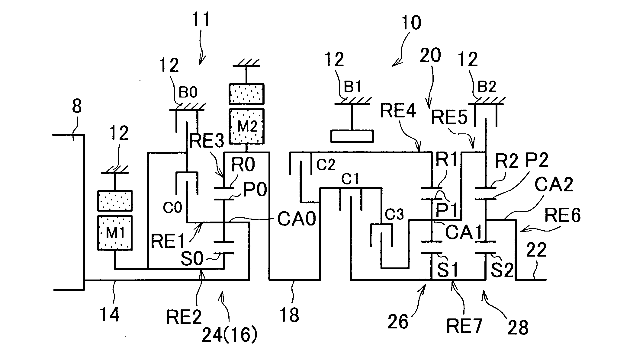
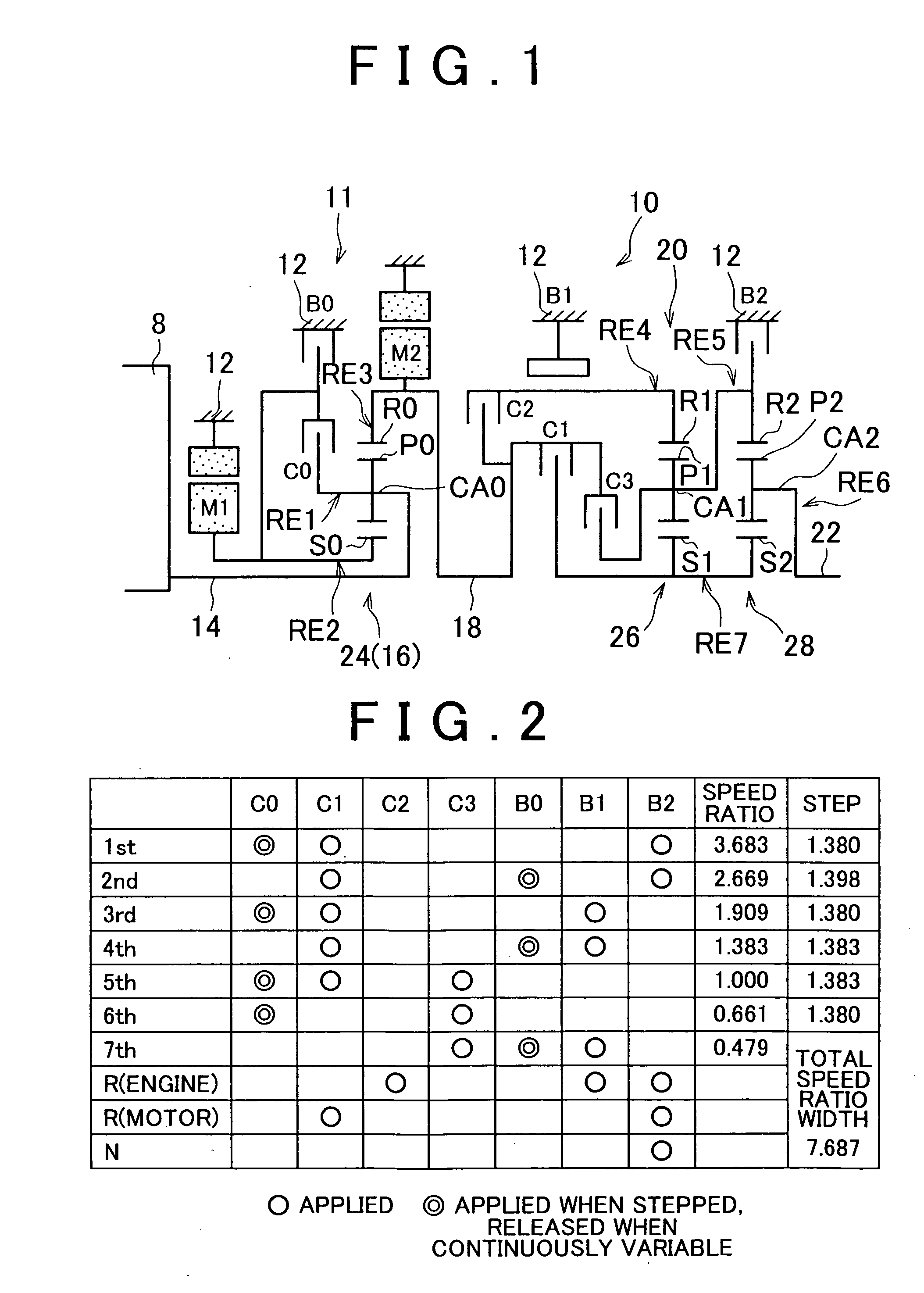
[0060]FIG. 1 is a skeleton view of shift mechanism (power transmitting apparatus) 10 that constitutes part of a power transmitting apparatus of a hybrid vehicle to which a control apparatus according to a first example embodiment of the invention can be applied. In FIG. 1, the shift mechanism 10 includes, in series, an input shaft 14, a differential portion 11, an automatic shifting portion 20, and an output shaft 22, all of which are arranged on a common axis inside a transmission case 12 which is a non-rotating member that is attached to the vehicle body (hereinafter this transmission case 12 will simply be referred to as “case 12”). The input shaft 14 is an input rotating member that is either directly connected to the engine 8 or indirectly connected to the engine 8 via a pulsation absorbing damper (i.e., a pulsation damping device), not shown, and the like. The differential portion 11 is a first transmitting portion or a continuously variable shifting portion that is connected ...

second example embodiment

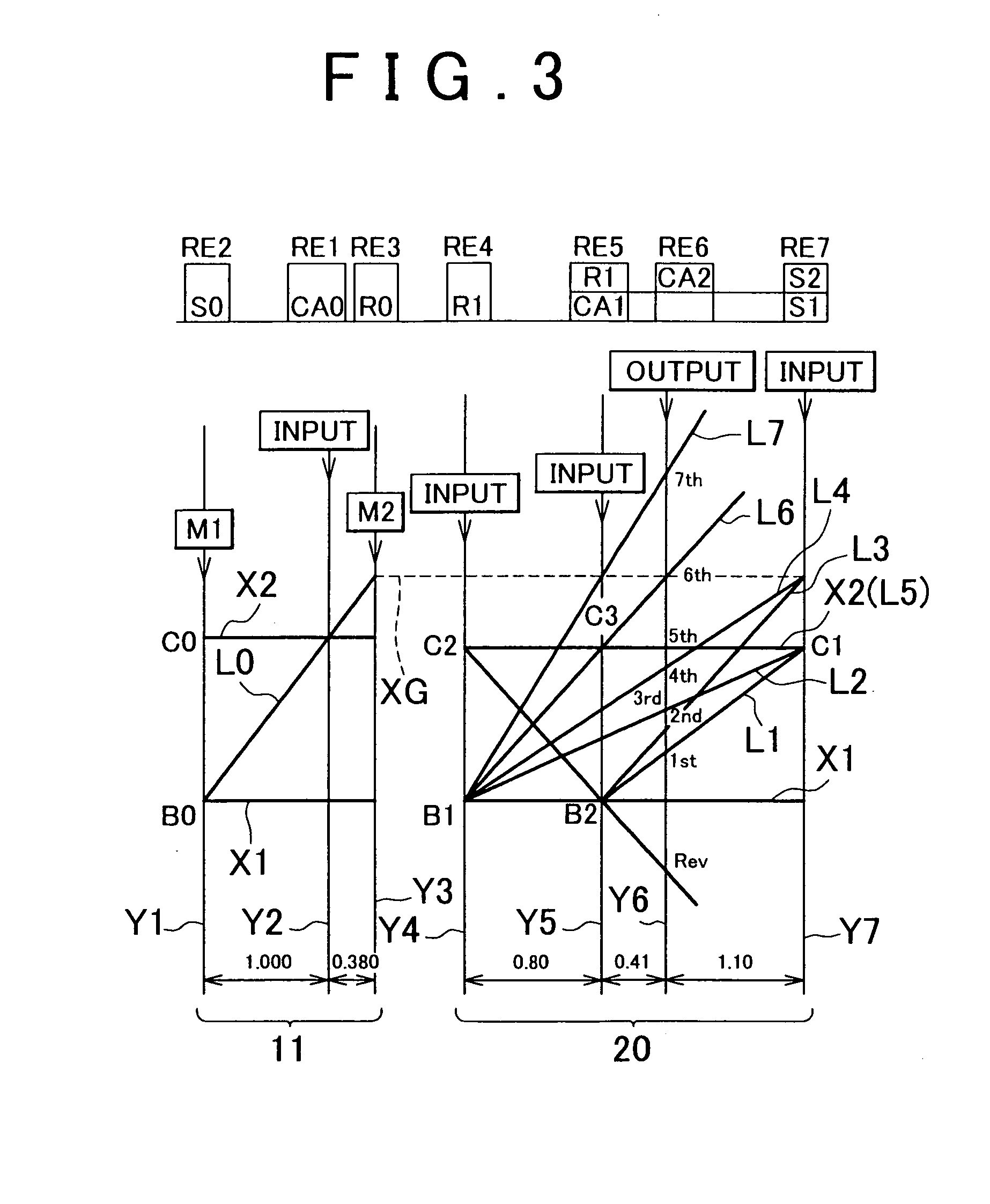
[0145]FIG. 11 is a skeleton view showing the structure of a shift mechanism 90 according to a second example embodiment of the invention. FIG. 12 is a clutch and brake application chart showing various application and release combinations of clutches and brakes (i.e., hydraulic friction apply devices) to achieve specific gears when the shift mechanism 90 is in a stepped shift state. FIG. 13 is an alignment graph illustrating the shift operations of that shift mechanism 90.

[0146]The shift mechanism 90 has i) a differential portion 11 that includes a first electric motor M1, a power split device 16, and a second electric motor M2, just as in the foregoing first example embodiment, which are all provided on a first axis RC1, and ii) a forward four-speed automatic shifting portion 94 provided on a second axis RC2 that is parallel to the first axis RC1. The power split device 16 has a single pinion type planetary gear set 24 having a predetermined gear ratio ρ0 of approximately 0.300, fo...


PUM


Abstract

A control apparatus for a vehicular power transmitting apparatus includes, in series, i) a differential portion which is provided with a differential mechanism having a differential function with respect to an input shaft and an output shaft, in which the differential mechanism is switched between a differential state and a non-differential state, and ii) a stepped shifting portion that shifts between a plurality of gears in a stepped manner. During a shift with a switch between the differential state and the non-differential state in the differential portion, the control apparatus either maintains the gear at that time or shifts into a gear that is adjacent to that gear.

Description

INCORPORATION BY REFERENCE[0001]The disclosure of Japanese Patent Application No. 2007-034157 filed on Feb. 14, 2007, including the specification, drawings and abstract is incorporated herein by reference in its entirety.BACKGROUND OF THE INVENTION[0002]1. Field of the Invention[0003]The invention relates to a vehicular power transmitting apparatus provided with a continuously variable shifting portion and a stepped shifting portion. More particularly, the invention relates to technology that is able to obtain a close ratio in which the change width of speed ratios is large (i.e., spans over a wide range) and in which the speed ratios are close together when the gear (i.e., gear speed) is changed in a stepped manner, while minimizing an increase in overall size of the vehicular power transmitting apparatus.[0004]2. Description of the Related Art[0005]Japanese Patent Application Publication No. 2005-206136 (JP-A-2005-206136) describes a vehicular power transmitting apparatus in which...

Claims


Application Information

Patent Timeline
IPC IPC(8): G06F19/00B60K6/445B60K6/543B60K6/547B60W10/10B60W20/00F16H59/42F16H59/44F16H59/70F16H61/02F16H61/68F16H61/684F16H61/686F16H63/50
CPCB60K1/02Y02T10/6239B60K6/40B60K6/445B60K6/54B60K6/547B60W10/06B60W10/08B60W10/115B60W20/00B60W2710/0666B60W2710/083B60W2710/1005F16H2037/0873Y02T10/56Y02T10/6286B60K6/365Y02T10/40Y02T10/62B60W2510/02B60W10/10B60W20/30B60W2050/004
Inventor TABATA, ATSUSHIMATSUBARA, TOORUSHIBATA, HIROYUKIKUMAZAKI, KENTA
Owner TOYOTA JIDOSHA KK
Why Eureka
Try Eureka