
Electrical machine with ferrofluid components

a technology of ferrofluid and components, applied in the field of electric machines, can solve the problems of high manufacturing complexity, substantial loss of iron, and high manufacturing complexity, and achieve the effect of high efficiency, substantial increase of slot fill factor, and high slot fill factor

Inactive Publication Date: 2008-08-21
SIEMENS AG
View PDF6 Cites 14 Cited by
  • Summary
  • Abstract
  • Description
  • Claims
  • Application Information

AI Technical Summary

Benefits of technology

[0015]Ferrofluids are superparamagnetic and have a very low hysteresis. The particles normally comprise iron, magnetite or cobalt and typically have a diameter of from 5 nm to 10 nm (nanometers). The surrounding liquid is, for example, oil or water, less often wax. In addition, surfactants are added to the liquid in order to achieve stability of the suspension.
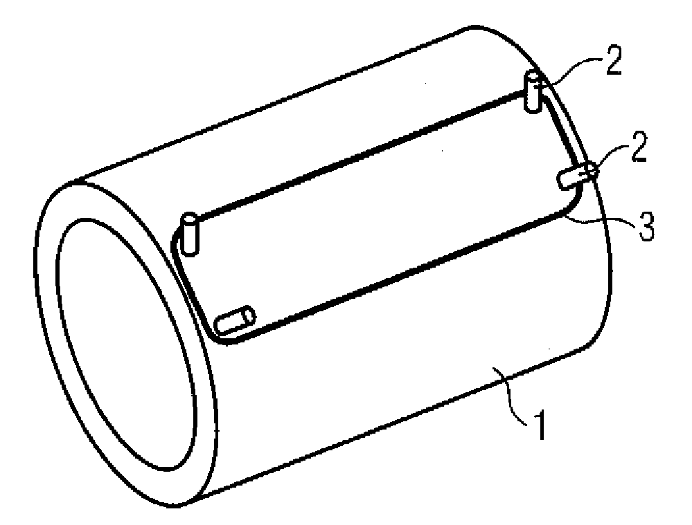
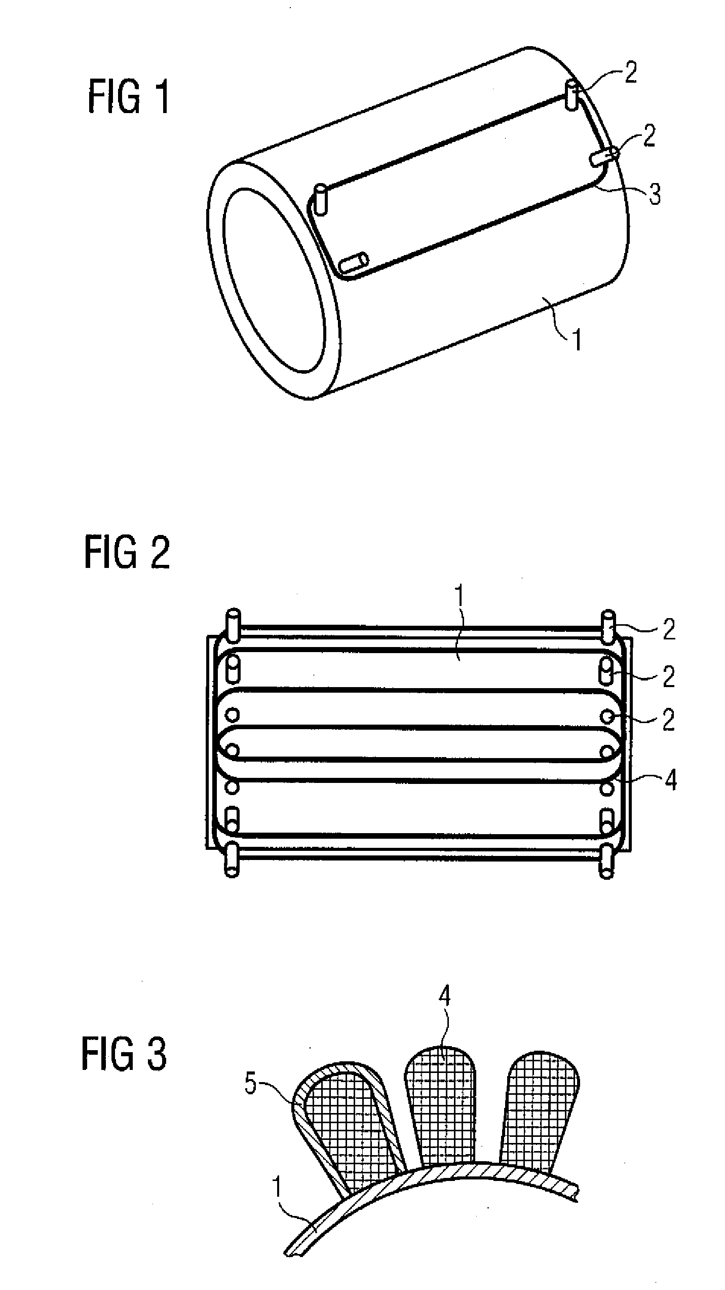
[0017]According to another feature of the present invention, the primary part may have a hollow-cylindrical winding support, with a single-phase or polyphase winding being arranged on the winding support. The winding can be fitted to the outer face of the hollow cylinder in the form of a concentrated winding (field-coil winding) or a distributed winding (lap winding). Suitably, the winding support has a plurality of pins for accommodating and fixing the winding. The pins may be arranged at the end-side regions of the hollow cylinder, so that the individual coils of the winding are wound around the pins. The production of the winding is simplified by the direct winding of the winding support since no coils need to be produced and then fitted separately. Furthermore, slots are not required for the winding since the coils are simply wound around the pins.
[0024]As a result of the use of flux-concentrating liquids, i.e. of ferrofluids, only very low remagnetization and eddy current losses occur in the primary part and / or secondary part, with the result that an electrical machine with a high degree of efficiency can be provided.
[0025]Since the winding is surrounded on all sides by the ferrofluid, an optimum magnetic main flux results since there are no air gaps in the primary and / or secondary part. The slot fill factor is therefore very high and is ideally 100%. In comparison with conventional machines, the slot fill factor is substantially increased, as a result of which the efficiency of the machine is likewise increased.
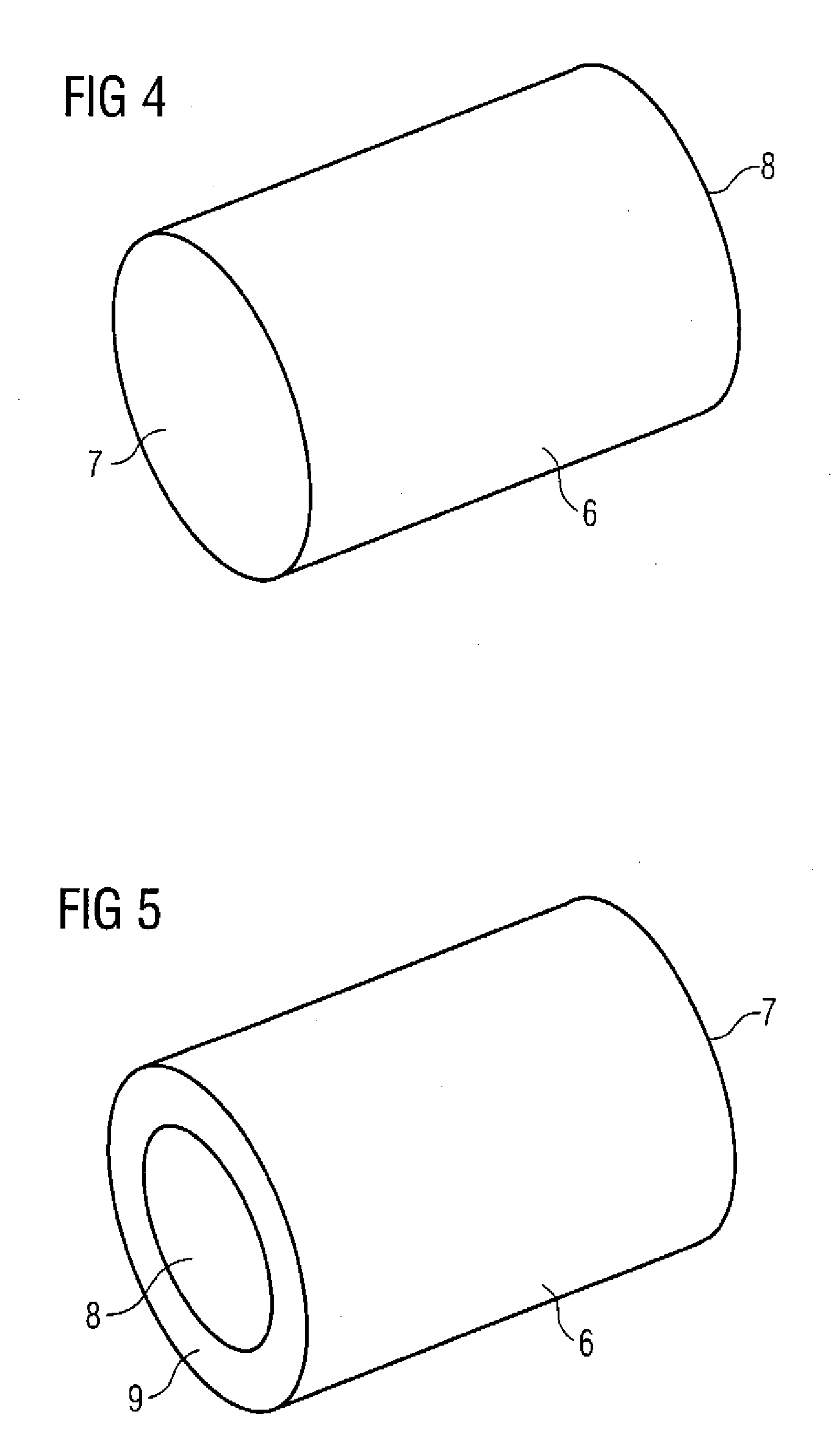
[0027]According to another feature of the present invention, the winding support (inner sleeve) and the outer sleeve may be plastic moldings, i.e. produced from plastic. The shaping for the primary and / or secondary part is therefore defined by moldings. This results in a simplified production process using few tools for the primary and / or secondary stack since the stamping of individual laminates and the stacking process are dispensed with. Furthermore, free shaping can be selected. The primary and / or secondary part can be produced, for example, by means of injection molding. As a result of the use of cost-effective injection-molded parts, complex and therefore expensive stamping techniques are no longer required.
[0029]Since the winding lies directly in the ferrofluid, the heat losses produced in the winding can be dissipated directly via the ferrofluid. As a result of this optimized dissipation of heat losses, the efficiency or the power of the electrical machine is increased.

Problems solved by technology

A high degree of manufacturing complexity results since suitable stamping dies, for example progressive dies, are required for stamping the individual laminates, various stamping dies being required for each embodiment of an electrical machine, such as two-pole, four-pole etc., for example.
In a laminate stack made from iron, substantially two types of losses occur.
Furthermore, iron losses occur as a result of eddy currents in the laminate stack.

Method used


Image

  • Electrical machine with ferrofluid components
  • Electrical machine with ferrofluid components
  • Electrical machine with ferrofluid components

Examples


Embodiment Construction

[0044]Throughout all the figures same or corresponding elements may generally be indicated by same reference numerals. These depicted embodiments are to be understood as illustrative of the invention and not as limiting in any way. It should also be understood that the figures are not necessarily to scale and that the embodiments are sometimes illustrated by graphic symbols, phantom lines, diagrammatic representations and fragmentary views. In certain instances, details which are not necessary for an understanding of the present invention or which render other details difficult to perceive may have been omitted.

[0045]Turning now to the drawing, and in particular to FIG. 1, there is shown a perspective view of a winding support 1 for a primary part 10 (not shown here) of an electrical machine 15 (FIG. 10) according to the invention. The winding support 1 is hollow-cylindrical and has a plurality of pins 2 for accommodating and fixing a winding. FIG. 1 shows an individual coil 3, whic...


PUM


Abstract

An electrical machine includes a primary part and a secondary part which are spaced apart from one another by an air gap and capable of moving relative to one another. The primary part and / or the secondary part is / are constructed for generating magnetic or electromagnetic fields, with the primary part and the secondary part having flux-concentrating means for guiding a magnetic main flux. At least portions of the magnetic main flux are guided by a ferrofluid.

Description

CROSS-REFERENCES TO RELATED APPLICATIONS[0001]This application claims the priority of German Patent Application, Serial No. 10 2007 007 559.8, filed Feb. 15, 2007, pursuant to 35 U.S.C. 119(a)-(d), the content of which is incorporated herein by reference in its entirety as if fully set forth herein.BACKGROUND OF THE INVENTION[0002]The present invention relates, in general to the filed of electrical machines.[0003]Nothing in the following discussion of the state of the art is to be construed as an admission of prior art.[0004]Electrical machines of a type involved here have a primary part and a secondary part which are capable of moving relative to one another. The secondary part may be, for example, a rotor of an electrical machine operating in rotary fashion or a moving part of a linear motor. The primary part is formed, for example, as a stator or as a fixed part with a single-phase or polyphase winding. In linear motors, both the primary part and the secondary part can be formed ...

Claims


Application Information

Patent Timeline
Patent Type & Authority Applications(United States)
IPC IPC(8): H02K9/00H02K1/00H02K21/12
CPCH02K1/12H02K1/02
Inventor WOHNER, NORBERT
Owner SIEMENS AG
Learn More