
Thermal Activation device, printer, thermal activation method, and method of producing a self-adhesive label

a self-adhesive label and activation device technology, applied in the direction of measuring devices, instruments, printing, etc., can solve the problems of excessive heat-sensitive adhesive sheet application, abnormal color development, difficult to set the trailing edge of heat-sensitive adhesive sheet, etc., to prevent the structure from increasing in size and complexity, prevent the adhesive force from being lowered, and prevent the effect of increasing costs

Inactive Publication Date: 2008-08-21
SEIKO INSTR INC
View PDF7 Cites 3 Cited by
  • Summary
  • Abstract
  • Description
  • Claims
  • Application Information

AI Technical Summary

Benefits of technology

[0010]It is an object of the present invention to provide a thermal activation device capable of preventing a heat-sensitive adhesive sheet from being partially excessively heated, keeping a short distance from a contact between a thermal head and a platen roller to a discharge port, and preventing the structure of the thermal activation device from being complicated and the size thereof from increasing, a printer including the thermal activation device, a thermal activation method, and a method of producing a self-adhesive label.
[0012]With the structure, the heat-sensitive adhesive sheet subjected to thermal activation by the thermal head is moved by the adhesion prevention member when the heat-sensitive adhesive sheet is not in contact with the platen roller and when the transporting force is not transmitted to the heat-sensitive adhesive sheet, thereby preventing the heat-sensitive adhesive sheet from being adhered to the thermal head. As a result, the heat-sensitive adhesive sheet is prevented from being excessively heated. In addition, there is no need to provide a particular transporting device between a contact between the thermal head and the platen roller, and the discharge port, and the distance between the contact between the thermal head and the platen roller, and the discharge port becomes shorter, which contributes to downsizing of the device and simplification of the structure thereof.
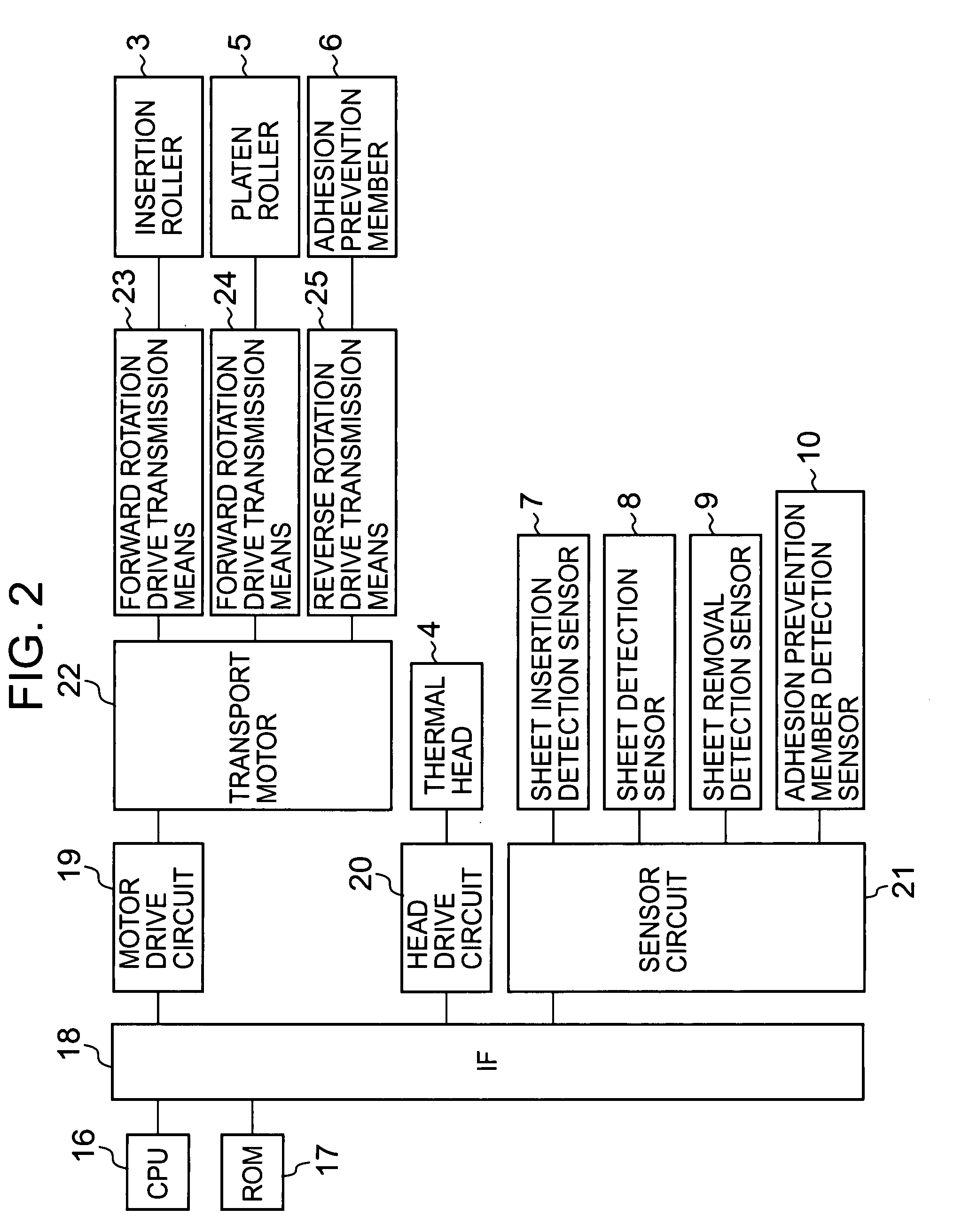
[0014]With the structure, the motor which is conventionally provided for driving the platen roller can be used for driving the adhesion prevention member, thereby simplifying the structure.
[0018]According to the present invention, the heat-sensitive adhesive sheet is not partially excessively heated, thereby preventing the adhesive force from being lowered, and the abnormal color development does not occur in a case where the heat-sensitive adhesive sheet has a recordable layer formed on one surface thereof. In addition, the present invention prevents the structure from increasing in size and from being complicated, and prevents costs from increasing.

Problems solved by technology

Even when driving of the thermal head is stopped, a residual heat remains in the thermal head, so the heat-sensitive adhesive sheet is continuously excessively applied with heat without being naturally cooled.
In addition, in a case where a recordable layer is formed on a surface opposite to the heat-sensitive adhesive layer, heat is excessively transmitted to the recordable layer, which may cause abnormal color development, for example, generation of a black line (stripe line).
In view of the above, it is difficult to set the trailing edge of the heat-sensitive adhesive sheet to be apart from the heat-generating portion of the thermal head as soon as the trailing edge thereof is apart from the platen roller.
Accordingly, it is impossible to prevent the heat-sensitive adhesive sheet from being partially excessively heated as described above.
Thus, it is difficult to transport the heat-sensitive adhesive sheet so as to reach the position at which the heat of the thermal head is not transmitted to the heat-sensitive adhesive sheet, only by transporting the heat-sensitive adhesive sheet through rotation of the platen roller.
However, in this case, there is a risk that the heat-sensitive adhesive sheet which has developed the adhesive force is adhered to the transport roller and cannot be transported to the discharge port.
If a force of the pair of discharge rollers for sandwiching the heat-sensitive adhesive sheet is reduced so that the heat-sensitive adhesive sheet is not adhered to the discharge roller, there is a risk that a sufficient transporting force cannot be transmitted to the heat-sensitive adhesive sheet and the heat-sensitive adhesive sheet cannot be transported to the discharge port after all.
However, in this case, it is necessary to provide a complicated and large structure between a contact between the thermal head and the platen roller, and the discharge port, with the result that the structure of the device is complicated and the size thereof is increased, and in addition, costs thereof increase.
Further, in a case where the distance between the contact between the thermal head and the platen roller, and the discharge port, becomes longer when the transporting device including the belt conveyor and the suction cup is provided, a distance by which the heat-sensitive adhesive sheet is transported also becomes longer.

Method used


Image

  • Thermal Activation device, printer, thermal activation method, and method of producing a self-adhesive label
  • Thermal Activation device, printer, thermal activation method, and method of producing a self-adhesive label
  • Thermal Activation device, printer, thermal activation method, and method of producing a self-adhesive label

Examples


Embodiment Construction

[0026]Hereinafter, embodiments of the present invention will be described with reference to the drawings.

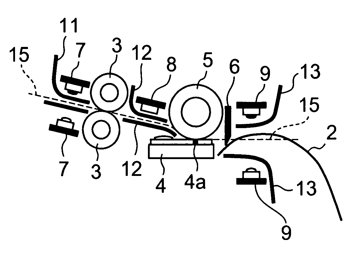
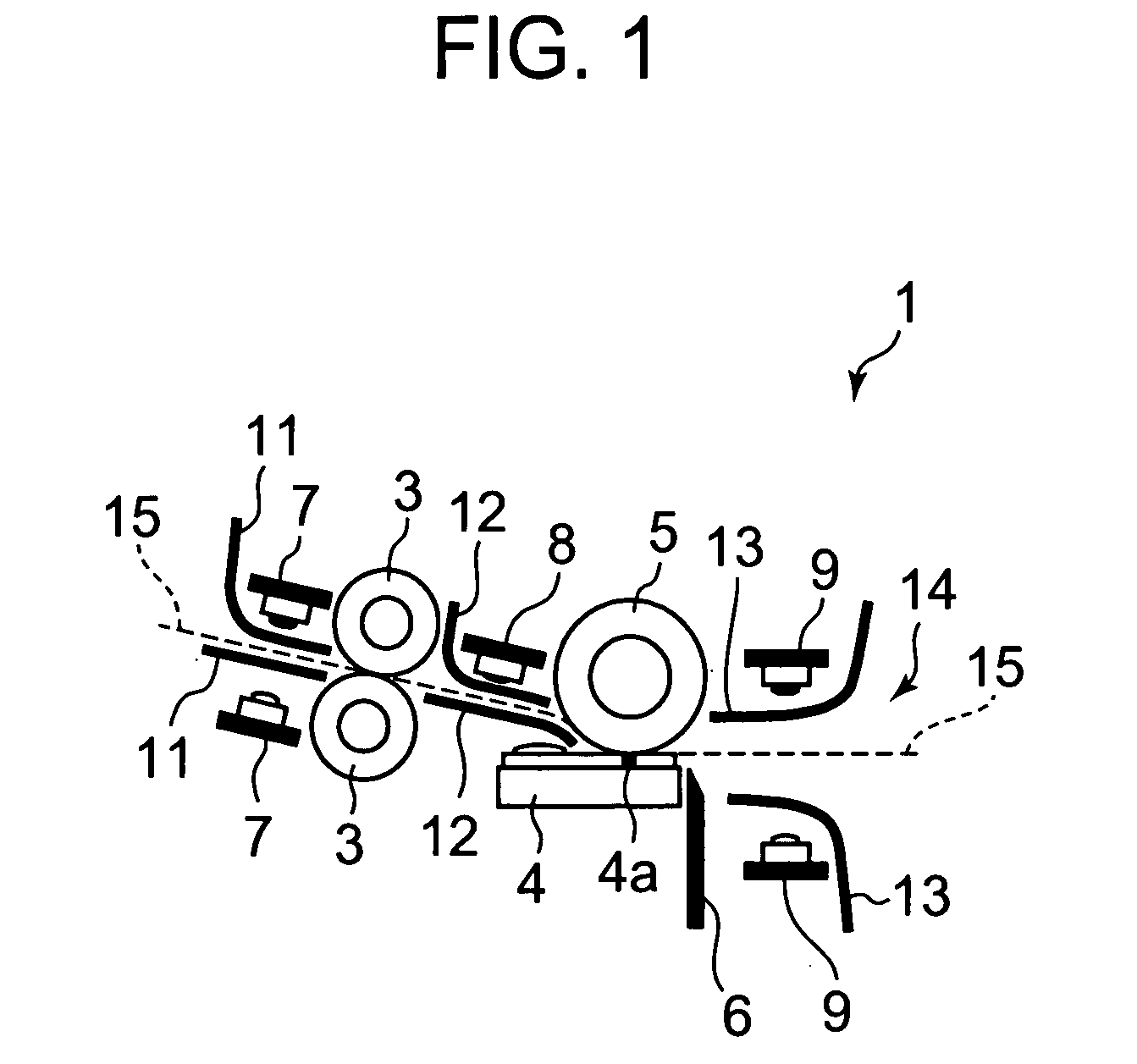
[0027]FIG. 1 is a schematic cross-sectional diagram showing a thermal activation device 1 according to an embodiment of the present invention. The thermal activation device 1 includes: a pair of insertion rollers 3 for introducing a heat-sensitive adhesive sheet 2 (see FIG. 4), which is to be subjected to thermal activation, into the thermal activation device 1; a thermal head 4 for heating and thermally activating a heat-sensitive adhesive layer of the heat-sensitive adhesive sheet 2; a platen roller 5 for sandwiching the heat-sensitive adhesive sheet 2 between the platen roller 5 and the thermal head 4; an adhesion prevention member 6 positioned at a downstream side of the thermal head 4; a plurality of sensors 7, 8, and 9; guide members 11, 12, and 13; and a discharge port 14.

[0028]Those members will be described in the order from an upstream side in a sheet transport directio...


PUM


Abstract

Provided is a thermal activation device capable of preventing a heat-sensitive adhesive sheet from being partially excessively heated, keeping a short distance between a contact between a thermal head and a platen roller, and a discharge port, and preventing a structure of the thermal activation device from being complicated and a size thereof from increasing. While a heat-sensitive adhesive sheet (2) is transported along a transport path (15) through rotations of insertion rollers (3) and a platen roller (5), a heat-generating portion (4a) of the thermal head (4) is caused to generate heat, thereby thermally activating a heat-sensitive adhesive layer of the heat-sensitive adhesive sheet (2). When a trailing edge of the heat-sensitive adhesive sheet (2) reaches a position where the trailing edge thereof is not in contact with the platen roller (5), a transporting force is not transmitted to the heat-sensitive adhesive sheet (2), thereby stopping transportation thereof. At that time, an adhesion prevention member (6) is allowed to enter the transport path (15) to lift and hold the trailing edge of the heat-sensitive adhesive sheet (2) to a position where the trailing edge thereof is not in contact with the thermal head (4).

Description

BACKGROUND OF THE INVENTION[0001]1. Field of the Invention[0002]The present invention relates to a thermal activation device for heating and thermally activating a heat-sensitive adhesive sheet so as to develop adhesive properties, a printer including the thermal activation device, a thermal activation method, and to a method of producing a self-adhesive label.[0003]2. Description of the Related Art[0004]Up to now, a heat-sensitive adhesive sheet having a heat-sensitive adhesive layer with adhesive properties to be developed by heat has been put to practical use. The heat-sensitive adhesive sheet has some advantages in that, for example, the heat-sensitive adhesive sheet can be easily treated because the sheet has no adhesive properties before being heated, and industrial waste is not produced because releasing paper is not used. In order to develop an adhesive force of the heat-sensitive adhesive layer of the heat-sensitive adhesive sheet, the heat-sensitive adhesive layer is heate...

Claims


Application Information

Patent Timeline
Patent Type & Authority Applications(United States)
IPC IPC(8): B41J2/325
CPCB41J2/32
Inventor OBUCHI, TATSUYA
Owner SEIKO INSTR INC
Learn More