Control arrangement for a resonant mode power converter

a power converter and control arrangement technology, applied in the direction of electric variable regulation, process and machine control, instruments, etc., can solve the problem of practicable upper limits of switching frequencies that can be used, and achieve the effect of reducing such dead times

Inactive Publication Date: 2008-08-21
POWER INTEGRATIONS INC
View PDF21 Cites 156 Cited by
  • Summary
  • Abstract
  • Description
  • Claims
  • Application Information

AI Technical Summary

Benefits of technology

[0021]It is desirable to minimize such dead times, which are provided between conduction times of complementary switches of a power converter for which simultaneous conduction must be avoided, for example in a half bridge power converter topology. This is especially the case where, for cascaded PFC and LLC converters in which each dead time determines a keep-out zone for switching of the PFC converter, this dead time limits the duty cycle range of the PFC converter. An optimum dead time is dependent upon a normal frequency range of the resonant mode converter, which may vary within a wide frequency band.
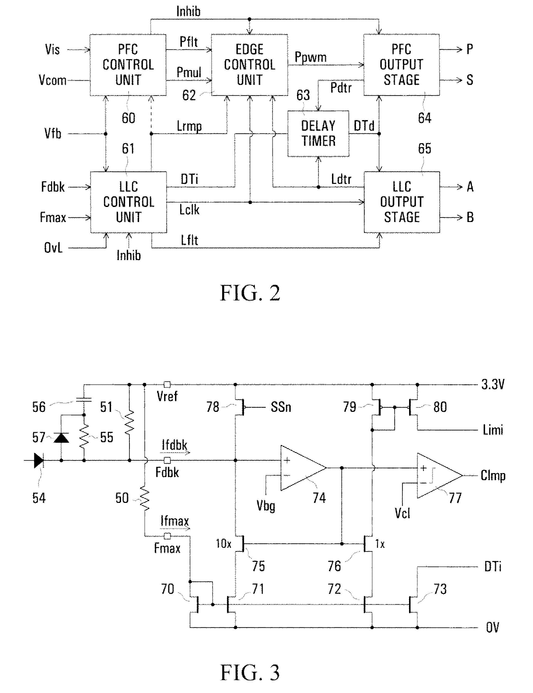
[0022]An embodiment of the Invention facilitates this by including the step of determining each dead time in dependence upon the second current.

Problems solved by technology

However, switching losses increase with increasing switching frequency, resulting in practical upper limits to the switching frequencies that can be used.
Furthermore, it is desirable that the dead times be minimized for any given switching frequency; this presents a problem in view of the wide range of possible switching frequencies of the LLC converter.

Method used


Image

  • Control arrangement for a resonant mode power converter
  • Control arrangement for a resonant mode power converter
  • Control arrangement for a resonant mode power converter

Examples


Embodiment Construction

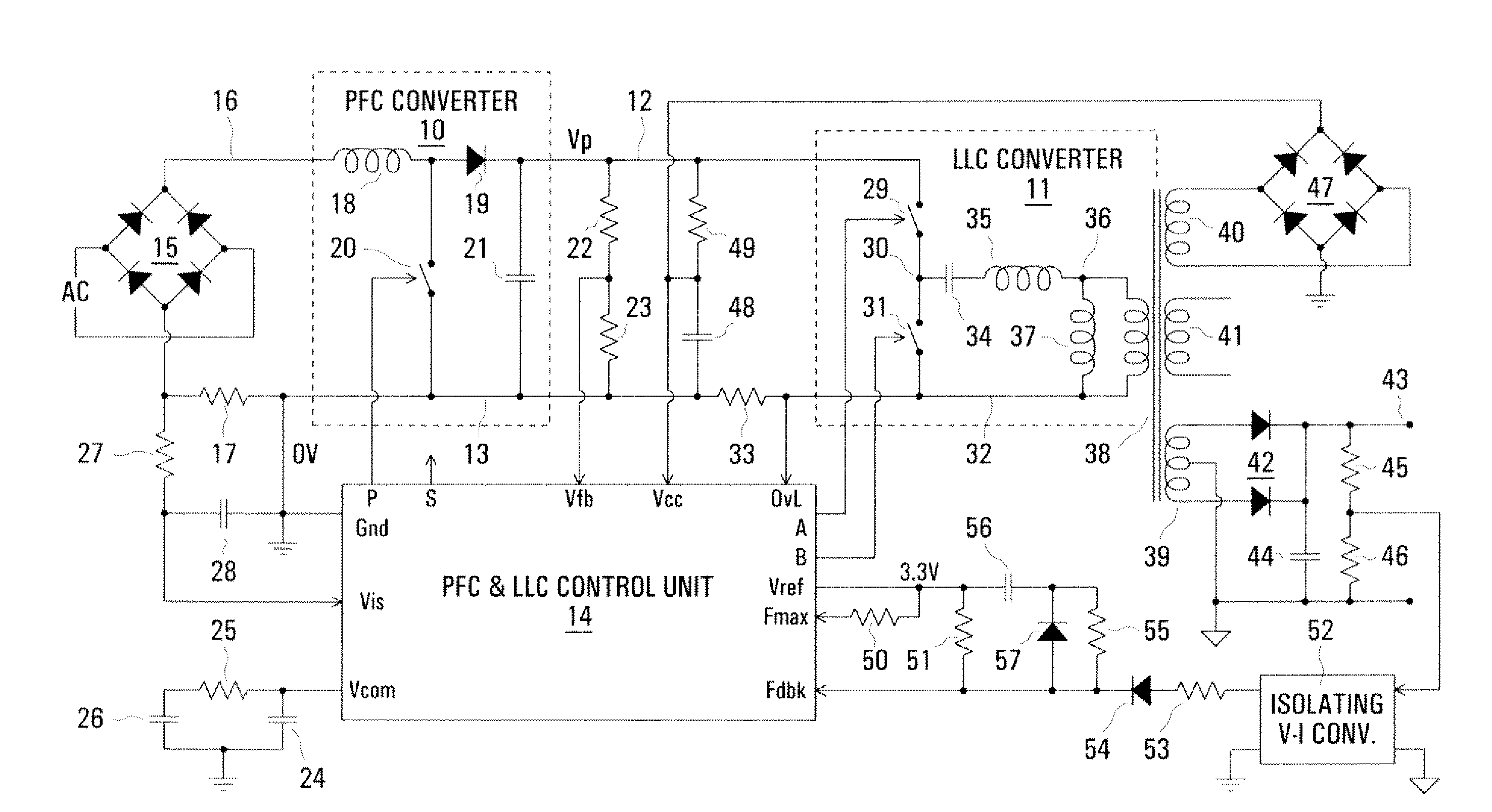
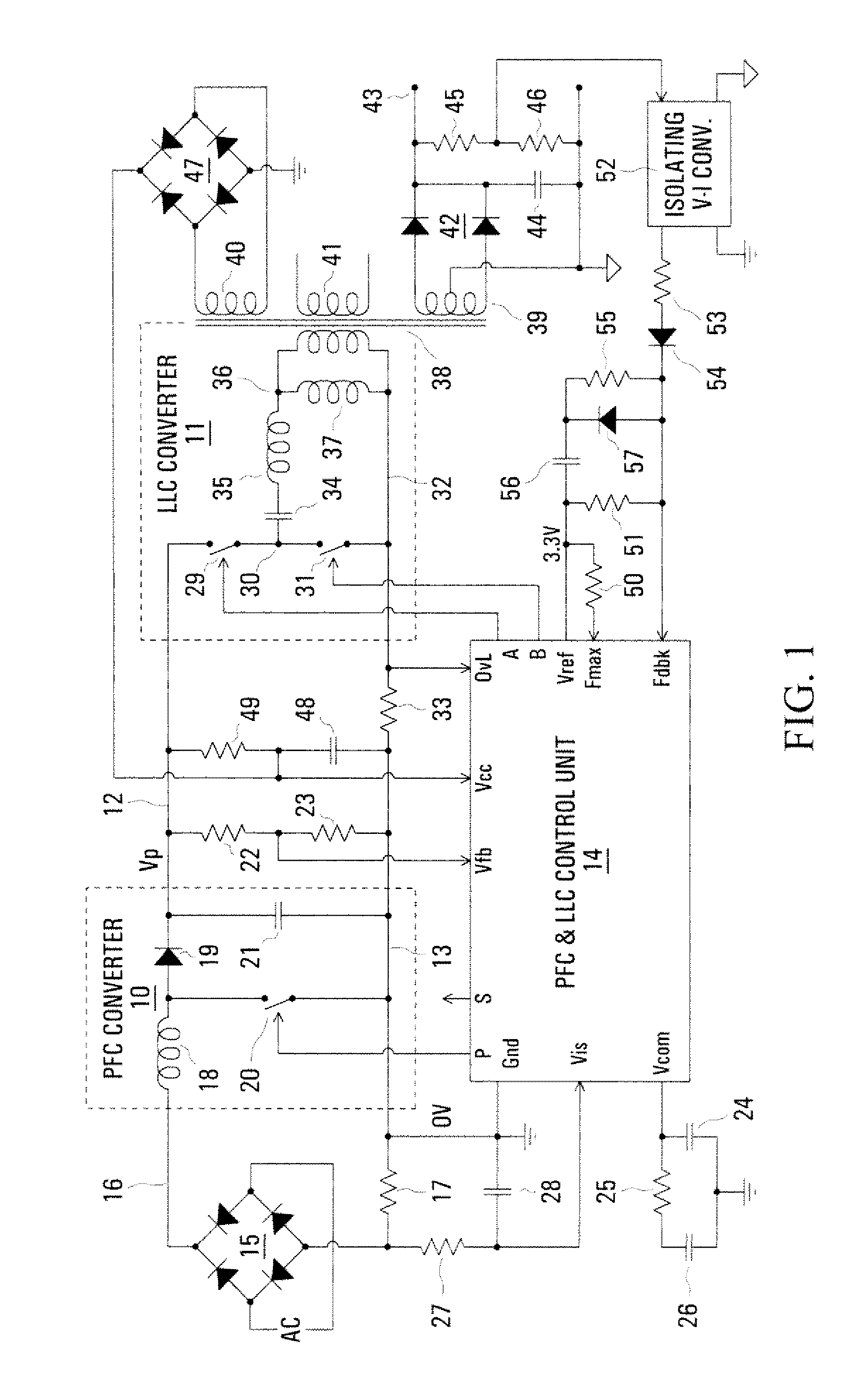
[0039]A power supply arrangement as illustrated in FIG. 1 includes a PFC power converter 10 and an LLC power converter 11, the converters being shown within broken line boxes. The converters 10 and 11 are cascaded, a positive output voltage Vp of the PFC converter 10, produced on a line 12 relative to a zero-volt (0V) line 13 connected to ground as shown, being connected as an Input voltage for the LLC converter 11. The cascaded PFC and LLC power converters 10 and 11 are controlled as described further below by a PFC and LLC control unit 14, which has a ground connection Gnd connected to the line 13.

[0040]AC power supplied to an input of the power supply arrangement is rectified by a diode bridge 15. A positive rectified AC output of the diode bridge 15 is coupled via a line 16 to a positive voltage input of the PFC converter 10, and a return path is provided from the 0V line 13 to the diode bridge 15 via a current sensing resistor 17. By way of example, the line 16 may have a peak ...


PUM


Abstract

The switching frequency of an LLC converter is controlled by a control unit to which a feedback circuit provides a first current dependent upon the output voltage of the converter. An oscillator circuit produces a sawtooth waveform at a frequency dependent upon the first current, up to a limit equal to a second current set by a resistor. Two complementary switch control signals are produced for controlling two switches of the converter for conduction in alternate cycles of the sawtooth waveform. A timer produces dead times between the two complementary switch control signals in dependence upon the second current. Another resistor provides a current constituting a minimum value of the first current, and a charging current of a capacitor in series with a resistor modifies the first current for soft starting of the converter.

Description

REFERENCE TO RELATED APPLICATIONS [0001]This application claims the benefit of U.S. Provisional Application No. 60 / 881,480 filed Jan. 22, 2007, entitled “Cascaded Power Converters And Control Arrangement Therefor”, the entire contents and disclosure of which are hereby incorporated herein by reference.[0002]Reference is directed to the following copending United States Patent Applications filed simultaneously herewith and claiming separate inventions, the entire contents and disclosure of each of which is hereby incorporated herein by reference:[0003]“Control Arrangement For A PFC Power Converter”, R. Colbeck et al., (PP046, 79115-65);[0004]“Cascaded PFC And Resonant Mode Power Converters”, R. Orr et ai., (PP048, 79115-64).[0005]This invention relates to a control arrangement for a resonant mode power converter.BACKGROUND [0006]It is known to provide a cascade of a boost converter for PFC followed by a PWM (pulse width modulation) buck converter for producing a lower voltage than th...

Claims


Application Information

Patent Timeline
Patent Type & Authority Applications(United States)
IPC IPC(8): H02M3/335H02M7/5383H02M7/00
CPCH02M3/3376Y02B70/1491H02M2001/0058Y02B70/1433Y02B70/10H02M1/0058
Inventor REINBERGER, ANTHONYDEMONE, PAUL
Owner POWER INTEGRATIONS INC
Why Eureka
Try Eureka