System and method for emergency brake control

a technology of emergency brakes and systems, applied in the direction of brake systems, brake components, transportation and packaging, etc., can solve the problems of delay in emergency brake response time, practical limits, jerk of rail cars, etc., to reduce or eliminate flow resistance, reduce overall dead time, and minimize jerk

Active Publication Date: 2020-08-06
KNORR BRAKE CO LLC
View PDF0 Cites 0 Cited by
  • Summary
  • Abstract
  • Description
  • Claims
  • Application Information

AI Technical Summary

Benefits of technology

[0006]Disclosed herein are systems and methods for regulating application of an emergency brake, for example on at least one truck of a rail vehicle, which systems and methods are configured to minimize jerk for riders' comfort while assuring safe application of the emergency brake. An emergency brake optimization module may be provided and positioned in fluid communication with a standard hydraulic brake system to regulate the application of the emergency brake. In certain exemplary configurations, the emergency brake optimization module may include a dead time caliper fill circuit, which circuit may be positioned in parallel to the emergency brake circuit, and particularly in direct fluid communication with the brake supply line extending from the emergency brake valve to the calipers of the brake system. The dead time caliper fill circuit may be configured to provide an initial inflow of hydraulic fluid to the brake supply line during a dead time period of fluid supply through the emergency brake valve, thus reducing the overall dead time experienced by the brake system during operation of the Emergency Brake mode. In other exemplary configurations, the emergency brake optimization module may include a secondary volume consumption circuit, which circuit may be placed in direct fluid communication with the brake supply line. In this configuration, an oversized choke, or optionally no choke, may be provided in the emergency brake circuit to decrease or eliminate flow resistance in the emergency brake circuit, and in turn minimize dead time experienced upon activation of the emergency brake, with jerk being controlled through consumption of excess hydraulic fluid by the secondary volume consumption circuit. In still further configurations, both a dead time caliper fill circuit and a secondary volume consumption circuit may be provided as described above to more precisely control reduction in dead time and minimization of jerk during application of the emergency brake.

Problems solved by technology

This process contributes to a delay in emergency brake response time.
Once the brake cylinders contact the disc, the brake pressure increases to the emergency brake setting, causing sudden deceleration and resultant jerk of the rail car.
However, a small choke carries disadvantages and practical limits, in that it increases the dead time and thus even further increases the emergency brake response time, and can easily be fouled by, for example, debris in the fluid system, increasing maintenance efforts and expense.

Method used


Image

  • System and method for emergency brake control
  • System and method for emergency brake control
  • System and method for emergency brake control

Examples


Embodiment Construction

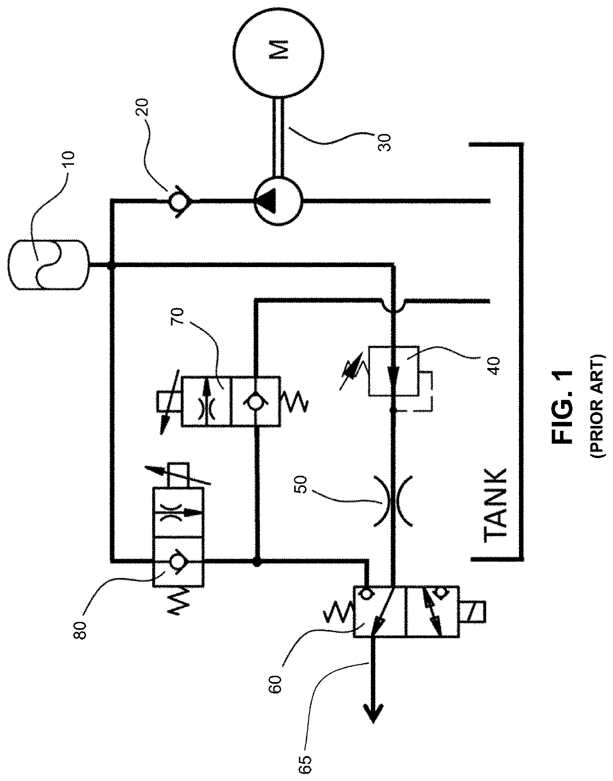
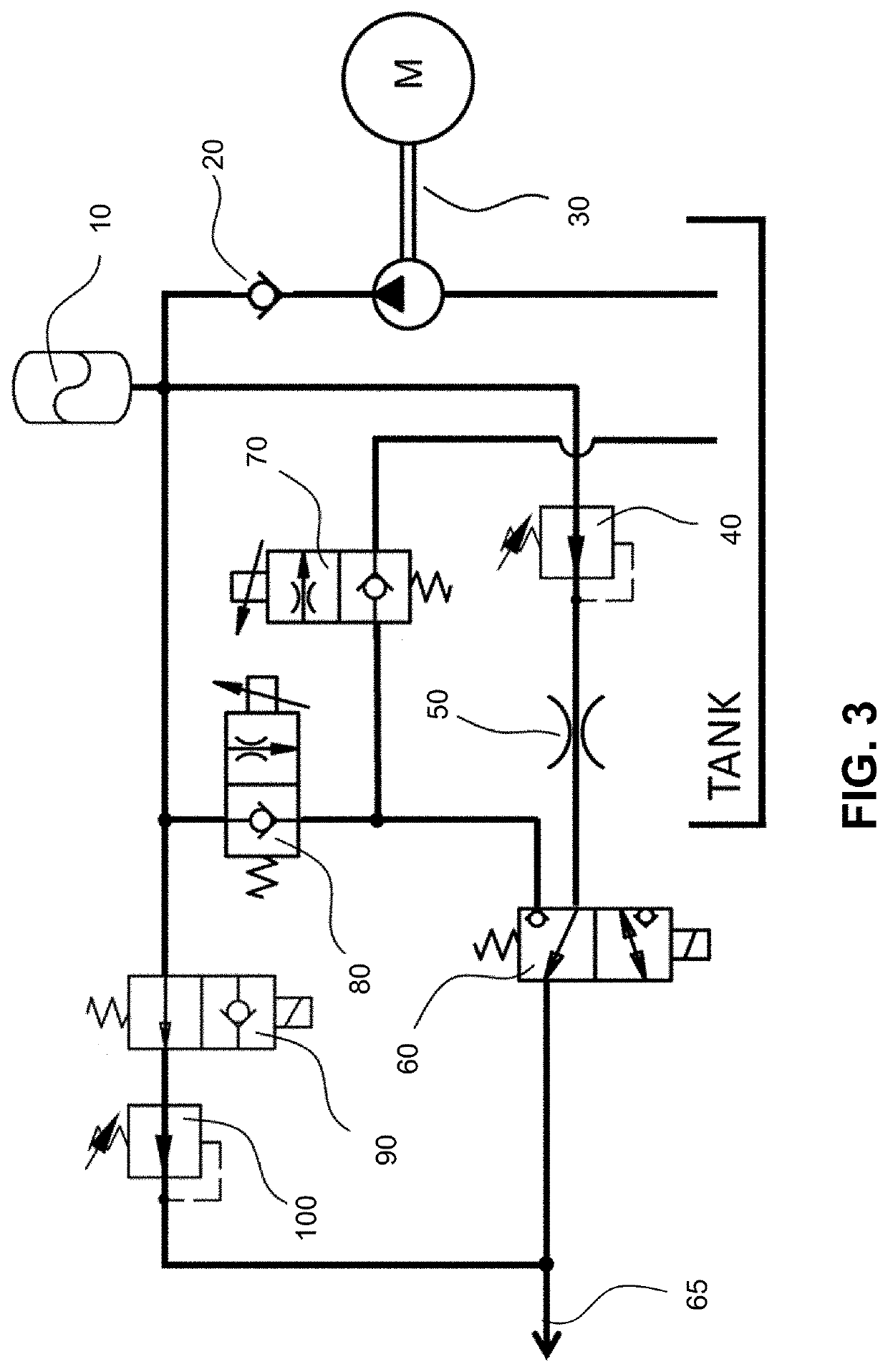
[0017]The invention may be understood by referring to the following description and accompanying drawings. This description of an embodiment, set out below to enable one to practice an implementation of the invention, is not intended to limit the preferred embodiment, but to serve as a particular example thereof. Those skilled in the art should appreciate that they may readily use the conception and specific embodiments disclosed as a basis for modifying or designing other methods and systems for carrying out the same purposes of the present invention. Those skilled in the art should also realize that such equivalent assemblies do not depart from the spirit and scope of the invention in its broadest form. The following descriptions detail the implementation range using active (pressure applied) calipers. Therefore, the hydraulic pressures are shown as increasing to a pressure reducing valve setting. Those skilled in the art will also recognize that passive calipers (spring applied, ...


PUM


Abstract

Disclosed are systems and methods for regulating application of an emergency brake configured to minimize jerk for riders' comfort while assuring safe application of the emergency brake. An emergency brake optimization module may be provided and positioned in fluid communication with a standard hydraulic brake system to regulate the application of the emergency brake through (i) providing an initial inflow of hydraulic fluid through a dead time caliper fill circuit to the brake supply line during a dead time period of fluid supply through the emergency brake valve to reduce dead time in emergency brake application, (ii) providing an oversized choke, or optionally no choke, in the emergency brake circuit with jerk being controlled through consumption of excess hydraulic fluid by a secondary volume consumption circuit, and (iii) providing both a dead time caliper fill circuit and a secondary volume consumption circuit to more precisely control reduction in dead time and minimization of jerk during application of the emergency brake.

Description

CROSS REFERENCE TO RELATED APPLICATION[0001]This application claims the benefit of U.S. Provisional Patent Application No. 62 / 801,360 titled “System and Method for Emergency Brake Control,” filed Feb. 5, 2019 by the Applicant noted herein, which application is incorporated herein by reference in its entirety.FIELD OF THE INVENTION[0002]This invention relates generally to the emergency braking function of hydraulic brake systems for vehicles, such as rail vehicles, and more particularly to systems and methods for regulating application of an emergency brake on a rail vehicle in order to minimize jerk for passenger comfort while ensuring proper and safe administration of the emergency brake. For reference, the European Standard EN 13452-1:2003 calls this type of emergency brake mode “Safety Brake” which, in comparison to lower integrity (usually software-controlled) Emergency Brake modes, requires a higher integrity level (availability). According to EN 13452-1:2003, the Safety Brake ...

Claims


Application Information

Patent Timeline
Patent Type & Authority Applications(United States)
IPC IPC(8): B61H13/20B60T13/68B60T15/02
CPCB60T15/021B61H13/20B60T2270/402B60T13/686B60T13/14B60T17/18B60T17/22B60T13/665B60T17/228
Inventor SELMER, JACOBMERSCHBECKER, UDOWINGATE, REGGIE
Owner KNORR BRAKE CO LLC
Why Eureka
Try Eureka