Control of a half-bridge

a half-bridge and control technology, applied in the direction of pulse technique, power conversion system, oscillation generator, etc., can solve the problems of increased stress on the switching device or on the electrical consumer, increased losses, and high power loss in the time between the switch-off of the one switching device, so as to minimize the dead time, reduce the stress, and minimize the effect of high power loss

Active Publication Date: 2016-05-05
ROBERT BOSCH GMBH
View PDF13 Cites 4 Cited by
  • Summary
  • Abstract
  • Description
  • Claims
  • Application Information

AI Technical Summary

Benefits of technology

[0013]The control device may also be configured to minimize a dead time during which neither the first nor the second switching device is being activated. A high power loss may occur in the time between switch-off of the one switching device and on the switch-on of the other switching device, in particular in an application in which an inductive load, such as an electric motor, is connected at the output, if the inductive component of the load forces a continuous current flow, which is diverted in a diode function of one of the switching devices. If field effect transistors, in particular MOSFETs, are used as the control devices, a current may also flow opposite to the forward direction if the transistor is blocking. If the activations of the switching devices are adapted dynamically to minimize the dead time, then an asymmetry between the switch-on times may occur or may be increased by this adaptation. The dead times may be minimized by taking into account the difference in the switch-on times without risking the described shift of the current in the load.

Problems solved by technology

In particular when the consumer includes an inductive or capacitive consumer, this shift may result in increased losses and increased stresses on the switching devices or on the electrical consumer.
A high power loss may occur in the time between switch-off of the one switching device and on the switch-on of the other switching device, in particular in an application in which an inductive load, such as an electric motor, is connected at the output, if the inductive component of the load forces a continuous current flow, which is diverted in a diode function of one of the switching devices.

Method used


Image

  • Control of a half-bridge
  • Control of a half-bridge
  • Control of a half-bridge

Examples


Embodiment Construction

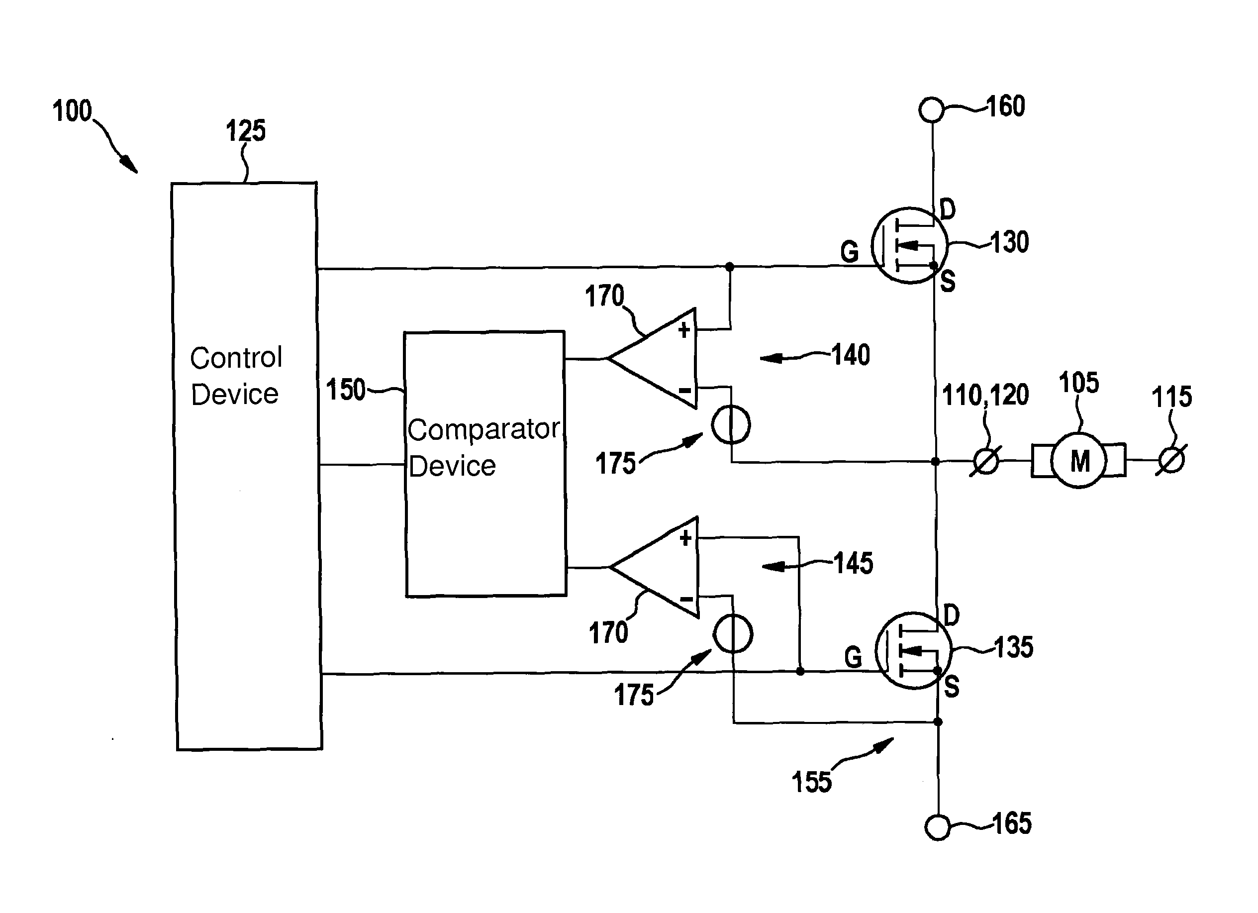
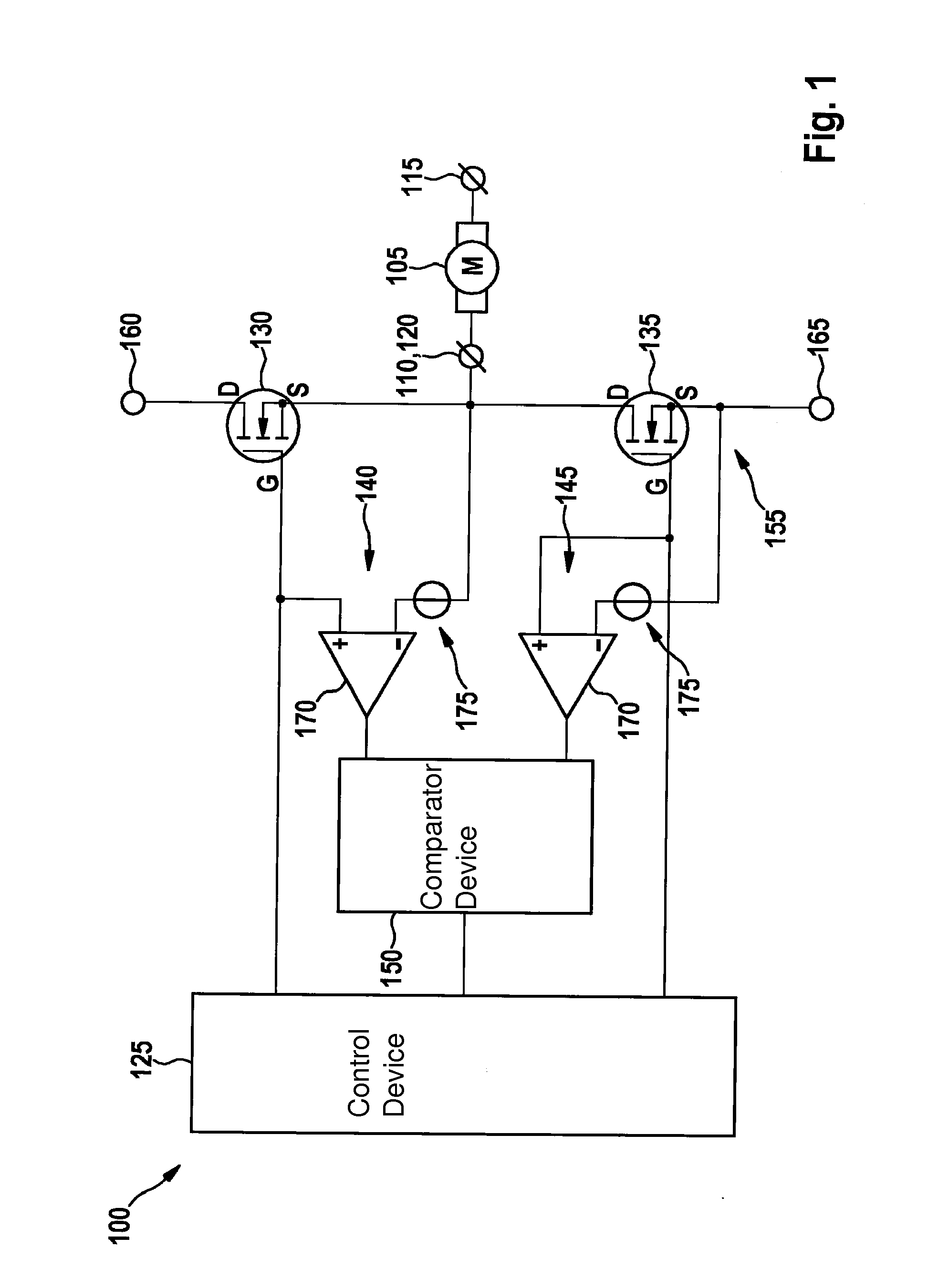
[0018]FIG. 1 shows a circuit diagram of a control 100 for an electrical consumer 105. Electrical consumer 105 includes a first terminal 110 and a second terminal 115 between which a current may flow. Control 100 includes a control device 125, a first switching device 130, a second switching device 135, a first scanning device 140, a second scanning device 145 and a comparator device 150.

[0019]Switching devices 130 and 135 together form a half-bridge 155. First switching device 130 is configured to control a current flow from a first potential 160 to output 120, and second switching device 135 is configured to control a current flow from output 120 to a second potential 165. In the specific embodiment illustrated here, first terminal 110 of consumer 105 is connected to output 120. Second terminal 115 of consumer 105 may be connected to a predetermined potential, which is preferably between the potentials 160 and 165 or to an additional half-bridge 155, for example, which is configure...


PUM


Abstract

A control for an electrical consumer includes a first switching device for connecting an output for the consumer to a first potential, a second switching device for connecting the output to a second potential, a control device for activating the switching devices, a first scanning device for providing a first signal as a function of a switching state of the first switching device, a second scanning device for providing a second signal as a function of a switching state of the second switching device, and a comparator device for determining a difference in the switch-on times of the switching devices on the basis of the determined signals.

Description

FIELD OF THE INVENTION[0001]The present invention relates to control of a half-bridge. In particular the present invention relates to a control device for controlling a consumer with the aid of a half-bridge.BACKGROUND INFORMATION[0002]An electrical consumer may be controlled with the aid of a half-bridge, which includes a first switching device for connecting the consumer to a positive potential and a second switching device for connecting the consumer to a negative potential. A second terminal of the consumer is usually at a predetermined potential, in particular ground, or may be controlled in a corresponding manner but with reverse polarity with the aid of an additional half-bridge. Some consumers, for example, brushless d.c. motors or polyphase three-phase a.c. motors, may require additional half-bridges.[0003]A control device is configured to always activate only one of the two switching devices to connect the consumer to the particular desired potential. For example, latency ...

Claims


Application Information

Patent Timeline
Patent Type & Authority Applications(United States)
IPC IPC(8): H03K17/687H02M1/08H02M1/00H02M1/38
CPCH02M1/08H03K17/687H02M1/38H03K17/165H03K17/18H02P7/04H02M1/0003H02M1/0009
Inventor JOOS, JOACHIMSCHIEMANN, WERNERHAUG, MARTIN
Owner ROBERT BOSCH GMBH
Why Eureka
Try Eureka