System and method of detecting phase body diode using a comparator in a synchronous rectified FET driver

a technology of synchronous rectified fet driver and comparator, which is applied in the direction of pulse manipulation, pulse technique, instruments, etc., can solve the problems of significant efficiency degradation and possible damage to the system, false detection, and difficulty in body diode detection, so as to improve efficiency and performance, the effect of minimizing the dead time between fet activation

Active Publication Date: 2005-06-16
INTERSIL INC
View PDF2 Cites 33 Cited by
  • Summary
  • Abstract
  • Description
  • Claims
  • Application Information

AI Technical Summary

Benefits of technology

[0009] In this manner, the initial phase node voltage level is sampled and stored and the voltage drop of the phase node relative to its initial level is compared with a predetermined amount for each cycle. Variations that might otherwise compromise detection of the state of the lower FET, such as the type of FET used, load conditions, temperature variations, etc., are compensated by sampling the initial phase voltage level. Thus, dead time between FET activations is minimized and becomes consistent from cycle to cycle thereby improving efficiency and performance.

Problems solved by technology

Simultaneous activation of both FETs results in significant efficiency degradation and possible damage to the system.
Body diode detection is challenging due to phase node variability mainly effected by the voltage drop when the FET is in the on state and the natural oscillation caused by immediate turn off of the FET.
In an attempt to reduce dead time, premature detection causes a false detection and late detection increases dead time.
Such variables have made it difficult to determine when the lower FET is off and when the upper FET should be activated.
This solution was somewhat unreliable and inconsistent.
The temperature, load and other variables resulted in significant variations from one cycle to the next or over time resulting in unpredictable results and significant inefficiencies.

Method used


Image

  • System and method of detecting phase body diode using a comparator in a synchronous rectified FET driver
  • System and method of detecting phase body diode using a comparator in a synchronous rectified FET driver
  • System and method of detecting phase body diode using a comparator in a synchronous rectified FET driver

Examples


Embodiment Construction

[0019] The following description is presented to enable one of ordinary skill in the art to make and use the present invention as provided within the context of a particular application and its requirements. Various modifications to the preferred embodiment will, however, be apparent to one skilled in the art, and the general principles defined herein may be applied to other embodiments. Therefore, the present invention is not intended to be limited to the particular embodiments shown and described herein, but is to be accorded the widest scope consistent with the principles and novel features herein disclosed.

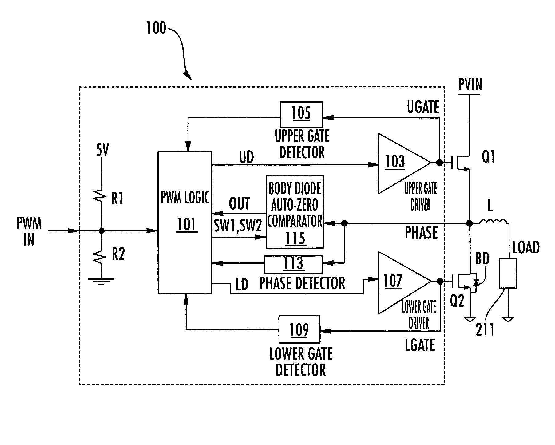
[0020] The present invention addresses the problem of reducing the phase body diode dead time and achieves consistent cycle-to-cycle dead time in dynamic mode of operation. A system and method of detecting phase body diode using an auto-zero comparator in a synchronous rectified MOSFET driver according to an embodiment of the present invention solves the problem of reducing t...


PUM


Abstract

A body diode comparator circuit for a synchronous rectified FET driver including a sample circuit and a comparator. The FET driver has a phase node coupled between a pair of upper and lower switching FETs and is responsive to a PWM signal having first and second phases for each cycle. The sample circuit samples an initial voltage of the phase node during the first phase of the PWM signal and provides a sum voltage indicative of the initial phase voltage added to the voltage level of the phase node during the second phase of the PWM signal. The comparator compares the sum voltage with a predetermined reference voltage and provides an output indicative of an activation state of the lower FET during the second phase of the PWM signal. The FET driver turns on the upper FET when the comparator indicates that the lower FET is off.

Description

CROSS-REFERENCE TO RELATED APPLICATIONS [0001] This application claims the benefit of U.S. Provisional Application No. 60 / 529,859 filed on Dec. 16, 2003, entitled “SYSTEM AND METHOD OF DETECTING PHASE BODY DIODE USING AN AUTO-ZERO COMPARATOR IN A SYNCHRONOUS RECTIFIED MOSFET DRIVER”, which is herein incorporated by reference for all intents and purposes.BACKGROUND OF THE INVENTION [0002] 1. Field of the Invention [0003] The present invention relates to PWM power regulators, and more particularly to a method of detecting phase body diode using an auto-zero comparator in a synchronous rectified MOSFET driver. [0004] 2. Description of the Related Art [0005] A synchronous rectified field-effect transistor (FET) driver for a power regular includes two switching FETs coupled in series between an input voltage signal and ground at an intermediate phase node. An output inductor has one end coupled to the phase node and its other end coupled to a load. A pulse-width modulation (PWM) feedback...

Claims


Application Information

Patent Timeline
Patent Type & Authority Applications(United States)
IPC IPC(8): H02M1/088H02M3/155H02M3/158H02M5/42H03K17/082H03K17/687
CPCH02M1/088H02M3/1588Y02B70/1466H03K17/6871H03K17/0822H02M1/38Y02B70/10
Inventor DEQUINA, NOEL B.PRESLAR, DONALD R.SFERRAZZA, PAUL K.
Owner INTERSIL INC
Why Eureka
Try Eureka