Extruder

a technology of extruder and extruder plate, which is applied in the direction of machines/engines, liquid fuel engines, rotary/oscillating piston pump components, etc., can solve the problem of relatively high filling pressure, and achieve the effect of simplifying construction and keeping the quality of extrudate constan

Inactive Publication Date: 2008-08-21
VMI AZ EXTRUSION
View PDF10 Cites 1 Cited by
  • Summary
  • Abstract
  • Description
  • Claims
  • Application Information

AI Technical Summary

Benefits of technology

[0016]The solution according to the invention therefore makes it possible by simple means to keep the quality of the extrudate constant, even when different masses, such as, on the one hand, synthetic rubber mixtures and, on the other hand, mixtures of natural rubber, are employed.
[0017]If viscous masses only within a relatively limited viscosity range are to be processed and construction is to be simplified, according to a further feature of the invention it is possible for the positive-displacement gear and the extruder screw to be connected frictionally or nonpositively. This avoids the need for a separate drive for the positive-displacement gear and / or the conveying gear.

Problems solved by technology

Epicyclic gear pumps, however, have the disadvantage that the filling pressure is relatively high due to the feed orifice and flow diversion.

Method used


Image

  • Extruder
  • Extruder
  • Extruder

Examples


Embodiment Construction

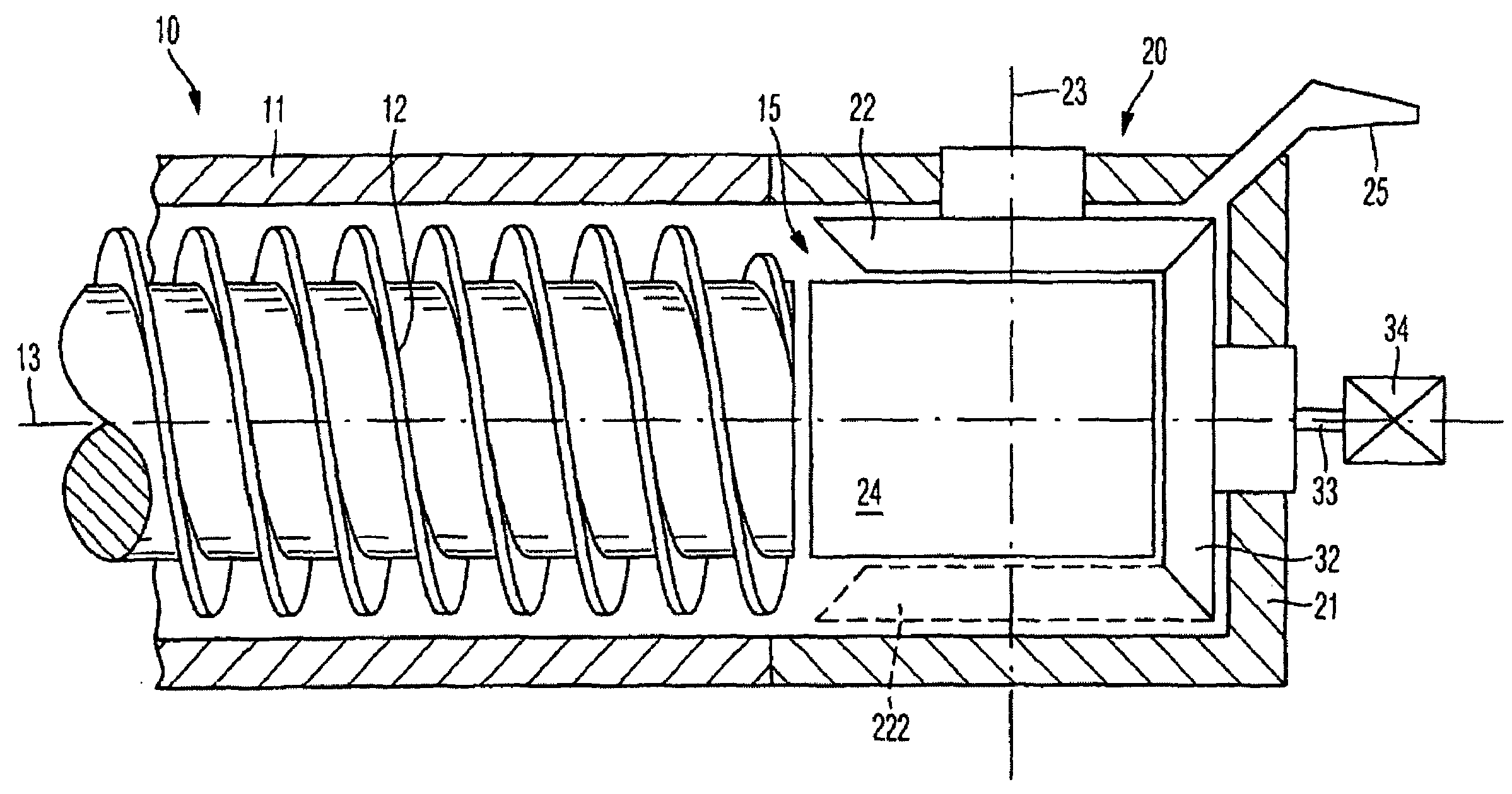
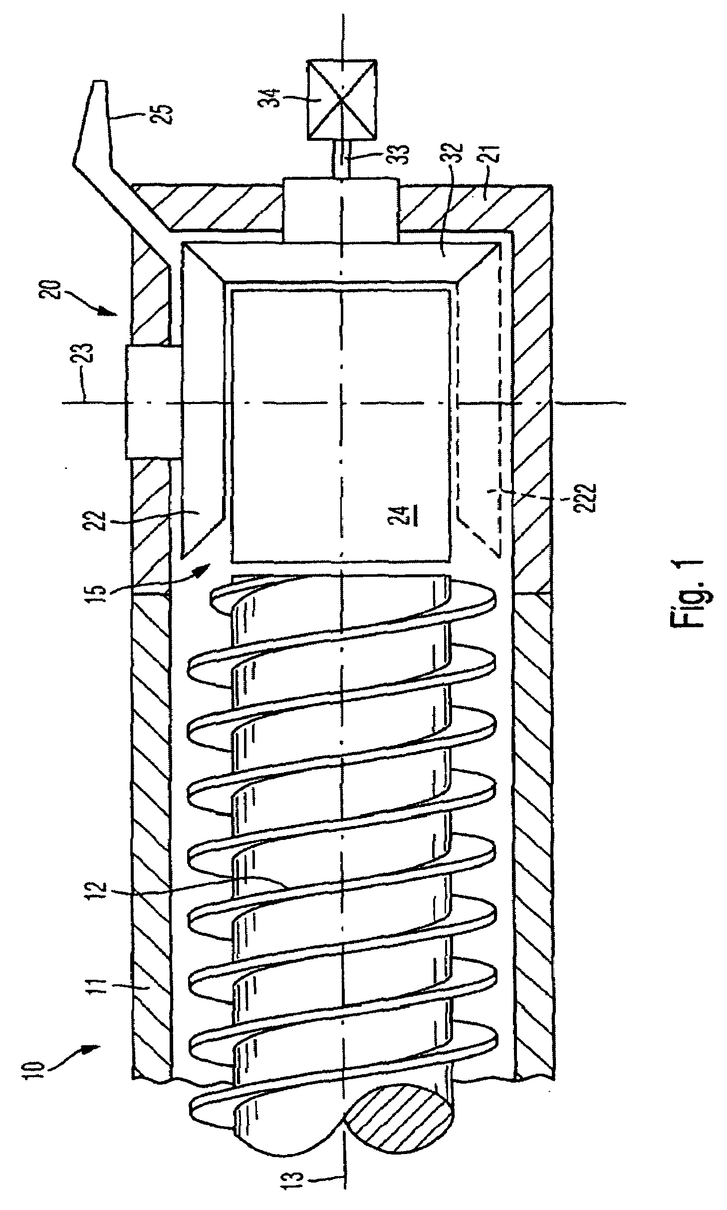
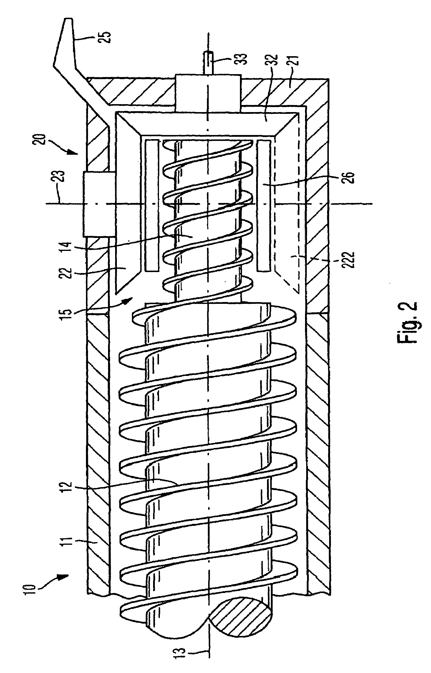
[0025]FIG. 1 shows diagrammatically, in longitudinal section, a worm or screw extruder 10 with an extruder housing 11 for receiving an extruder worm or screw 12 of conventional construction.

[0026]The extruder housing 11 is followed by a positive-displacement gear pump 20 arranged in a housing 21 which is likewise illustrated only diagrammatically.

[0027]Within the housing 21 is arranged a conveying gear 22 which is mounted rotatably about an axis 23.

[0028]A positive-displacement gear 32 meshes with the conveying gear 22 and, in the exemplary embodiment illustrated, is arranged coaxially with the axis 13 of the extruder screw 12. In the exemplary embodiment illustrated, the positive-displacement gear 32 is rotatable independent of the screw 12, the axis 33 of the positive-displacement gear 32 being designed as a shaft having a positive-displacement gear drive 34.

[0029]In the exemplary embodiment illustrated in FIG. 1, the extruder screw 12 extends as far as an insert 24 within the hou...


PUM

PropertyMeasurementUnit
viscousaaaaaaaaaa
anglesaaaaaaaaaa
acute angleaaaaaaaaaa

Abstract

An extruder for viscous masses, and including an extruder screw and a positive-displacement gear pump disposed downstream of the extruder screw as viewed in the conveying direction. The positive-displacement gear pump has at least one conveying gear and at least one positive-displacement gear. The axis of the conveying gear is disposed essentially at right angles to the axis of the extruder screw, and the axis of the positive-displacement gear is disposed essentially in the same direction as the axis of the extruder screw.

Description

BACKGROUND OF THE INVENTION[0001]The present invention relates to an extruder for viscous masses, in particular thermoplastic melts and natural or synthetic rubber mixtures, and includes an extruder screw which is followed in the conveying direction, downstream, by a positive-displacement gear pump having at least one conveying gear and at least one positive-displacement gear.[0002]In extruders of this type, it is known to arrange a gear pump, generally with two rotors, behind the extruder screw downstream in the conveying direction. The gear pump requires a separate drive and is flanged to the housing of the extruder screw, in which case narrowed portions may occur as a consequence of construction at the transition between the two housings.[0003]The gear pumps are suitable for building high pressure gradients. They operate according to the volumetric conveyance principle in that the tooth cavities form closed-off chambers. Expulsion is virtually independent of the counterpressure a...

Claims


Application Information

Patent Timeline
Patent Type & Authority Applications(United States)
IPC IPC(8): B01F7/00B29C48/38B29C48/395B29C48/50B29C48/52B29C48/67
CPCB29C47/0019B29C47/367F04C3/04B29C47/364F04C15/06B29C47/6012B29C47/6018F04C11/006B29C48/07B29C48/37B29C48/387B29C48/52B29C48/53
Inventor UPHUS, REINHARD
Owner VMI AZ EXTRUSION
Why Eureka
Try Eureka