Double-Decker Pellicle-Mask Assembly

a double-decker, pellicle-mask technology, applied in the field of double-decker pellicle-mask assembly, can solve the problems of destroying the circuit pattern, affecting the quality of pellicle-masks, and affecting the appearance of pellicle-masks,

Inactive Publication Date: 2008-08-21
TAIWAN SEMICON MFG CO LTD
View PDF5 Cites 8 Cited by
  • Summary
  • Abstract
  • Description
  • Claims
  • Application Information

AI Technical Summary

Problems solved by technology

The mask may be easily damaged such as by dropping of the mask, the formation of scratches on the mask surface, electrostatic discharge (ESD), and particles.
ESD can cause discharge of a small current through the chromium lines on the surface of the mask, melting a circuit line and destroying the circuit pattern.
For wavelengths shorter than 193 nm, the existing materials used for soft pellicles are not suitable.
Hard pellicles are difficult to manufacture and to mount on a flat planar surface of a mask.
Because of these strict requirements, hard pellicles are very expensive.
In some extreme cases, a high-quality hard pellicle is more expensive than the mask to which the pellicle is attached.
Another drawback of hard pellicles is their fragility.
Furthermore, hard pellicles are easy to damage during the mounting and dismounting processes.
This is especially true of relatively thin hard pellicles, which are usually too fragile to survive the dismounting process.

Method used


Image

  • Double-Decker Pellicle-Mask Assembly
  • Double-Decker Pellicle-Mask Assembly
  • Double-Decker Pellicle-Mask Assembly

Examples


first embodiment

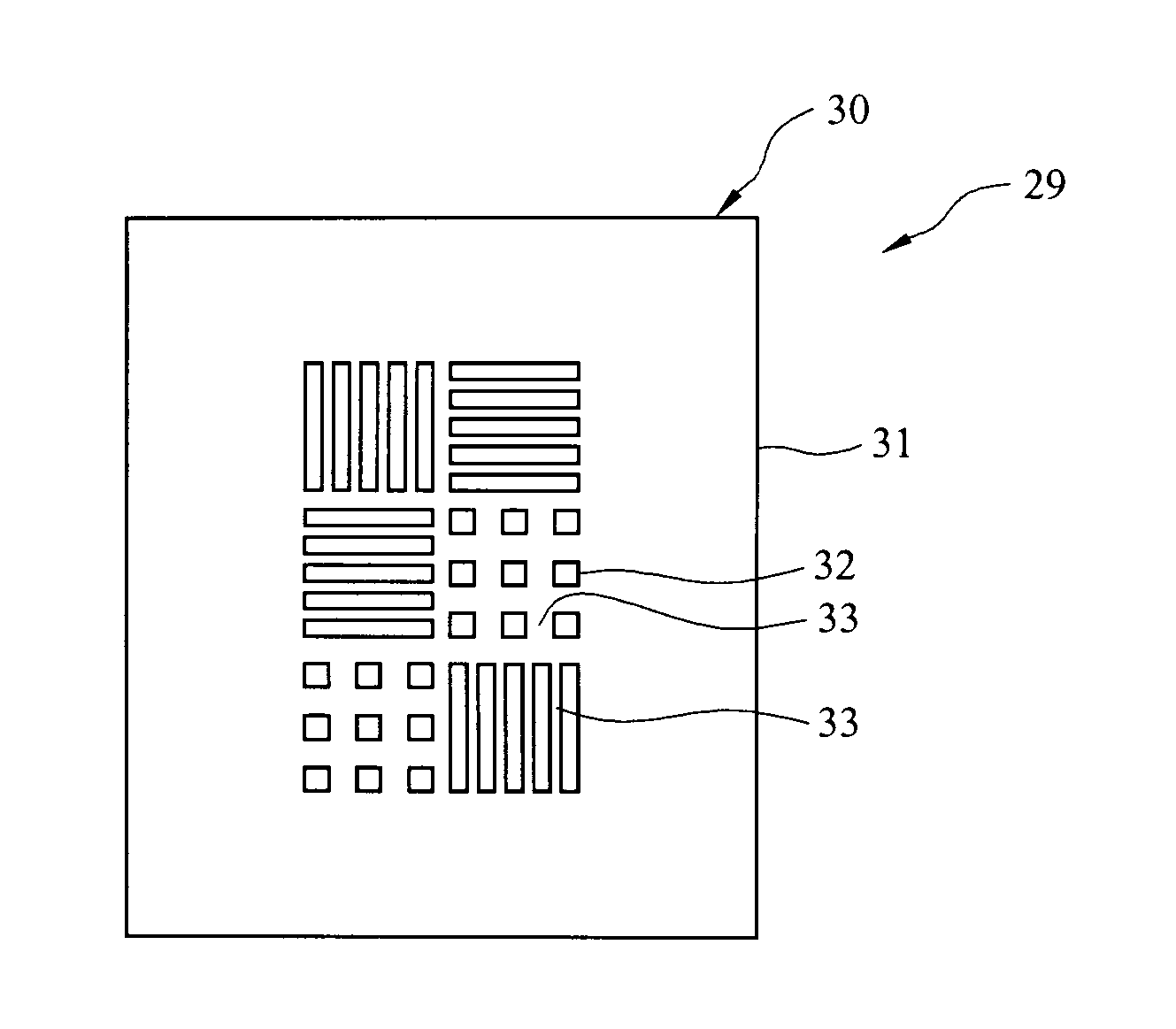
[0032]Referring initially to FIGS. 5 and 6, a pellicle-mask assembly of the present invention is generally indicated by reference numeral 29. The pellicle-mask assembly 29 includes a mask 30 having a transparent substrate 31 which may be quartz, for example. An absorber pattern and / or phase-shift pattern 32 is formed on the surface of the substrate 31 using techniques known by those skilled in the art. In fabrication of the pellicle-mask assembly 29, a hard pellicle 34, having a transparent pellicle body 35 such as quartz, is secured against the absorber pattern 32. In this regard, the assembly 29 does not have any structure that physically connects the pellicle body 35 and the mask substrate 31 so that they are not able to move relative to each other. Instead, they are coupled through use of a vacuum.

[0033]More specifically, the hard pellicle 34 is preferably a relatively thick hard pellicle, with a thickness of at least about 1 mm. Accordingly, attachment of the hard pellicle 34 t...

second embodiment

[0035]Referring next to FIGS. 7-10, a pellicle-mask assembly of the present invention is generally indicated by reference numeral 39 and includes a mask 40 having a transparent substrate 41 and an absorber pattern and / or phase-shift pattern 42 on the surface of the substrate 41. In fabrication of the pellicle mask assembly 39, a hard pellicle 44, having a transparent pellicle body 45, is secured against the absorber pattern 42 using a vacuum, and this step may be carried out in a conventional vacuum chamber (not shown). In the fabricated pellicle-mask assembly 39, vacuum spaces 43 exist between the mask substrate 41 and the pellicle body 45 in the interstices defined by the absorber pattern 42. A sealing frame 46, which may be plastic, for example, is interposed between and sealingly engages the mask substrate 41 and the pellicle body 45 along the edges or perimeter of the absorber pattern 42. Atmospheric air pressure urges the pellicle 44 against the mask 40 so as to fixedly couple...

third embodiment

[0036]Referring next to FIGS. 9-10, a pellicle-mask assembly of the present invention is generally indicated by reference numeral 39a. The pellicle-mask assembly 39a in FIG. 9 is similar to the pellicle-mask assembly 39 of FIGS. 7-8, except that the sealing frame 46a is made of rubber. Another alternative material for the sealing frame 46 is an oxide.


PUM

PropertyMeasurementUnit
thicknessaaaaaaaaaa
wavelength exposuresaaaaaaaaaa
wavelengthsaaaaaaaaaa

Abstract

A pellicle-mask assembly includes a mask substrate having an absorber pattern, and a hard pellicle held against movement with respect to the mask substrate by gas pressure.

Description

FIELD OF THE INVENTION[0001]The present invention relates generally to photolithography techniques for integrated circuit fabrication and, more particularly, to pellicles which reduce the propagation of defects in integrated circuits by shielding a mask from particles during photolithography.BACKGROUND OF THE INVENTION[0002]Various processing steps are used to fabricate integrated circuits on a semiconductor wafer. These steps include: deposition of a conducting layer on the silicon wafer substrate; formation of a photoresist or other mask such as titanium oxide or silicon oxide, in the form of the desired metal interconnection pattern, using standard lithographic or photolithographic techniques; subjecting the wafer substrate to a dry etching process to remove the conducting layer from the areas not covered by the mask, thereby etching the conducting layer in the form of the masked pattern on the substrate; removing or stripping the mask layer from the substrate typically using rea...

Claims


Application Information

Patent Timeline
Patent Type & Authority Applications(United States)
IPC IPC(8): G03F1/00
CPCG03F1/48G03F1/64G03F1/62
Inventor CHANG, SHIH-MINGHSIEH, HUNG-CHANGLIN, BURN JENG
Owner TAIWAN SEMICON MFG CO LTD
Why Eureka
Try Eureka