
Marked tools

a technology of markings and tools, applied in the field of surgical tools, can solve the problems of time-consuming and limited steps of accessing the bone, and achieve the effect of facilitating detection

Active Publication Date: 2008-08-21
DEPUY SYNTHES PROD INC
View PDF99 Cites 87 Cited by
  • Summary
  • Abstract
  • Description
  • Claims
  • Application Information

AI Technical Summary

Benefits of technology

[0015]In an exemplary embodiment of the invention, the series of gaps are characterized by known axial dimensions with respect to reamer and are placed at known positions on the (e.g. at a known distance from a distal end of the reamer drill). Optionally, a user of the tool evaluates a position of an end of the cannula relative to the series of gaps. In an exemplary embodiment of the invention, this evaluation aids in inserting the cannula to a desired depth by helping to judge a distance from an anatomic landmark (e.g. cannula end is 12 mm from a distal side of a vertebra). Optionally, translational motion of the cannula with respect to the reamer can cover and / or uncover a portion of the gaps. In an exemplary embodiment of the invention, a number of exposed gaps is an indicator of relative axial position of the cannula with respect to the reamer drill.
[0016]In various exemplary embodiments of the invention, the tool is adapted for percutaneous spinal surgeries, such as fixation of vertebral body fractures or intervertebral disc surgeries (e.g. for gaining access into the disc). Optionally, a small difference in outer diameter between the reamer drill and the cannula makes it possible to insert the cannula and reamer drill together and / or minimize soft tissue and / or bone damage.

Problems solved by technology

When minimally invasive surgery is involved, such as percutaneous surgery, the step of accessing the bone is limited by dimensional requirements.
As can be seen, accessing the bone is a multiple-stage procedure, which is time consuming.

Method used


Image

  • Marked tools
  • Marked tools
  • Marked tools

Examples


Embodiment Construction

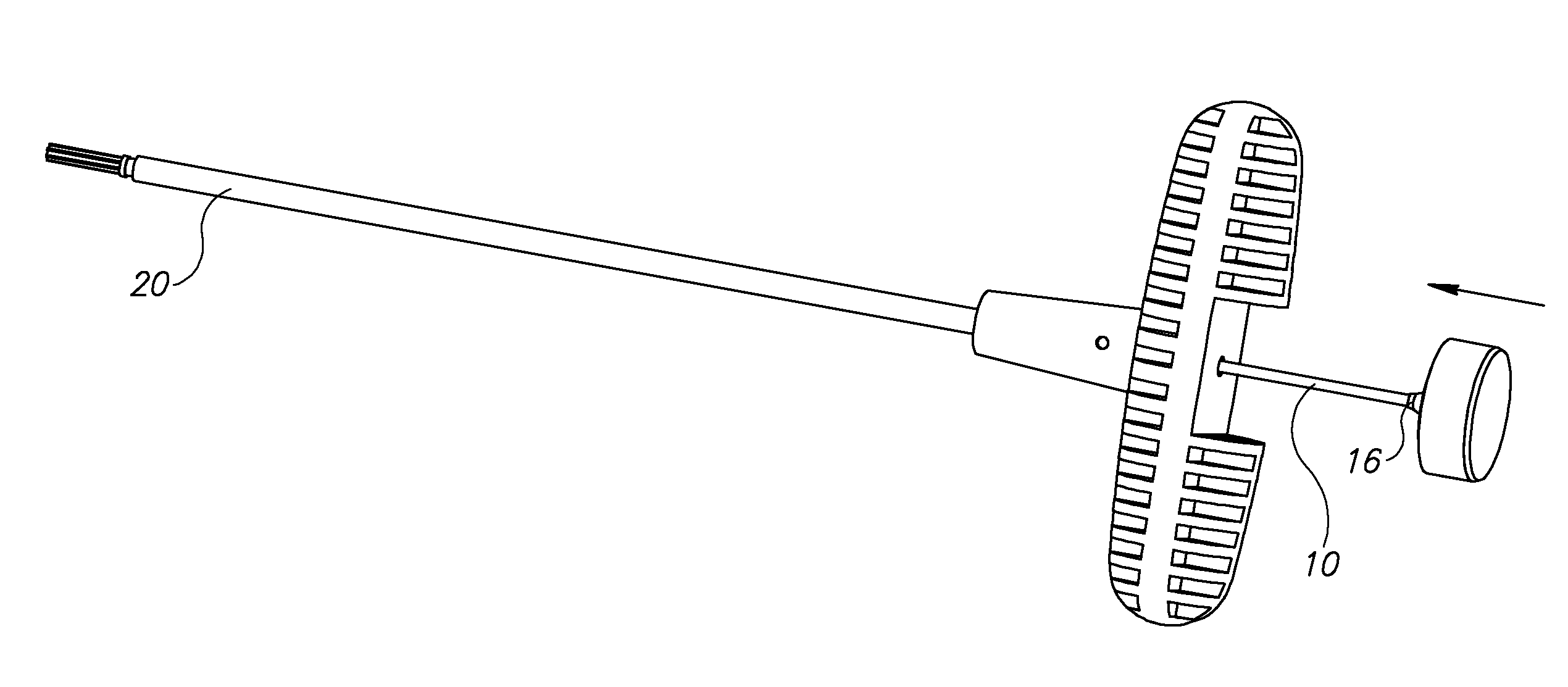
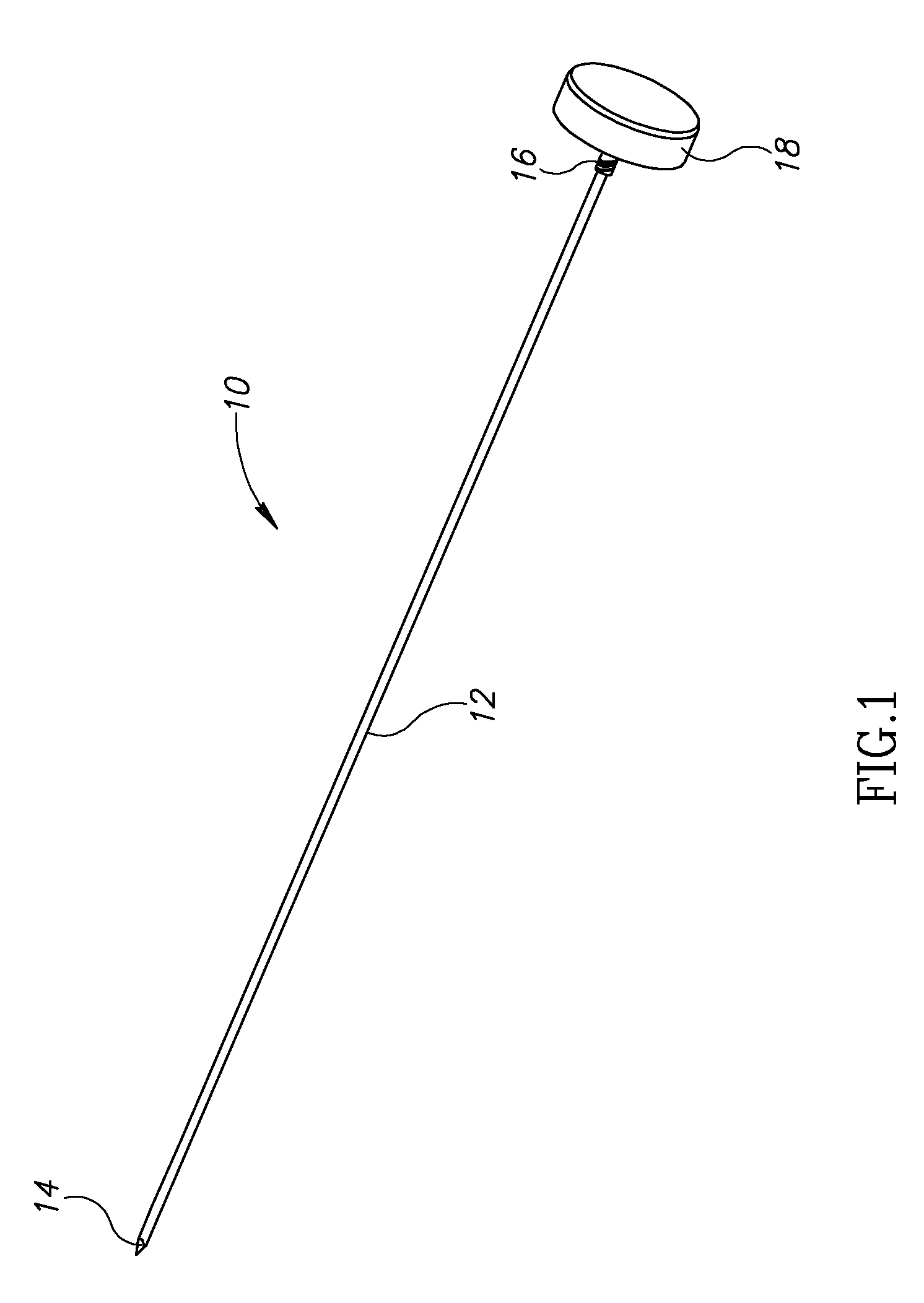
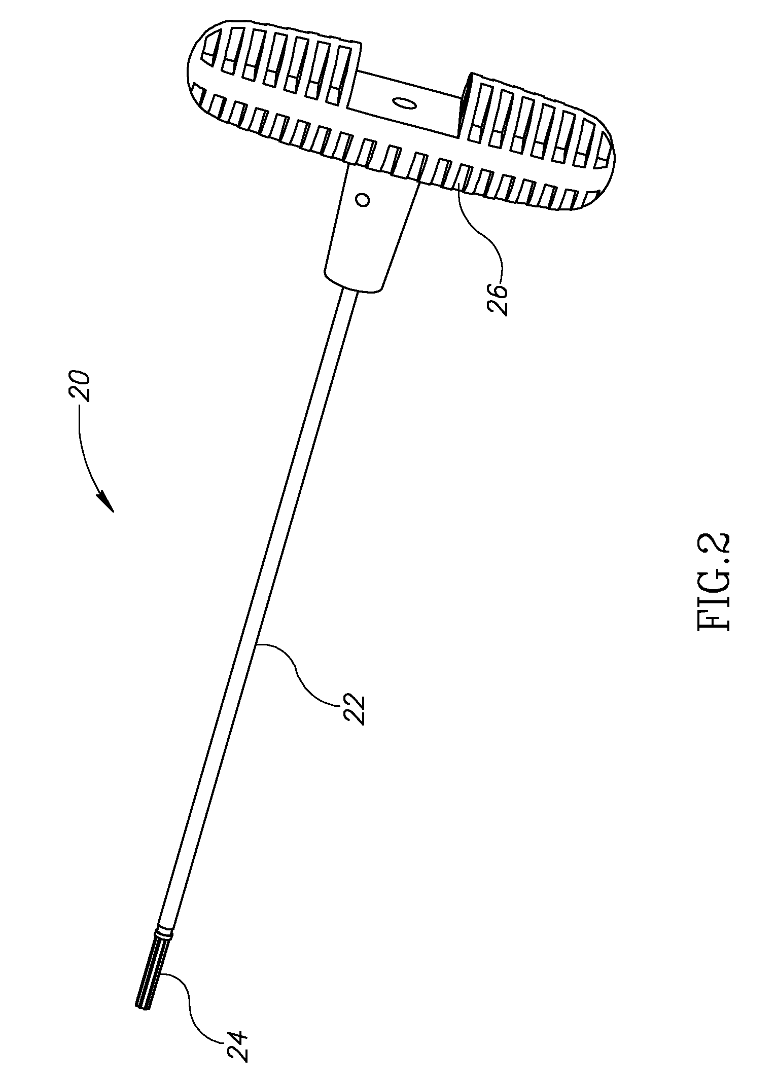
[0070]FIG. 1 illustrates an exemplary stylet 10 suitable for an exemplary bone access device 40 (FIG. 4), in accordance with some exemplary embodiments of the invention. Optionally, stylet 10 can be replaced by a guidewire. Stylet 10 is depicted as a tubular rod 12, having a pointed distal end 14 adapted to puncture and penetrate skin, soft tissue and / or cortical bone. Distal end 14 may be, for example, of diamond type, bevel type or J-type. Exemplary embodiments of stylet 10 designed for use with fractured vertebral body are optionally characterized by a diameter of about 1.4-2.2 mm. These exemplary embodiments of stylet 10 can optionally be inserted into the vertebral pedicle (up to about 2 mm in the vertebral body). In an exemplary embodiment of the invention, a proximal end of stylet 10 includes a thread 16. Optionally, thread 16 is compatible with matching threads on a reamer 20 (FIG. 2). In an exemplary embodiment of the invention, thread 16 is operable during assembly of styl...


PUM


Abstract

A surgical apparatus, the apparatus comprising: (a) a cutting tool comprising an axial member with a proximal end and a distal end, the axial member characterized by at least two adjacent axial sections, wherein differences between each of the sections are visually discernible when viewed in a projection x-ray image; and (b) a hollow tube adapted for parallel alignment with the cutting tool and selectively axially positionable to be adjacent at least a selective one of said axial sections and block x-ray radiation from at least one of passing through or passing adjacent said selected section so that said projection indicates a relative axial position of said hollow tube and said cutting tool.

Description

RELATED APPLICATIONS[0001]This application claims the benefit under 35 U.S.C. § 119(e) of U.S. provisional patent application 60 / 720,725 filed Sep. 28, 2005 and entitled “Tools and Methods for Treating Bones” the disclosure of which is fully incorporated herein by reference.[0002]This application is a continuation in part of PCT application IL2005 / 000812 filed Jul. 31, 2005, published as WO 2006 / 011152 and entitled “Materials, Devices and Methods for Treating Bones and Other Tissues” and of U.S. patent application Ser. No. 11 / 194,411 filed Aug. 1, 2005 and entitled “Materials, Devices and Methods for Treating Bones and Other Tissues” the disclosures of which are fully incorporated herein by reference.[0003]This application is related to U.S. provisional patent application 60 / 646,539 filed Jan. 25, 2005 and entitled “Tools and Methods for Treating Bones” the disclosure of which is fully incorporated herein by reference.FIELD OF INVENTION[0004]The present invention relates to surgical...

Claims


Application Information

Patent Timeline
IPC IPC(8): A61B17/16
CPCA61B17/1637A61B17/1671A61B17/3472A61B2017/00902A61B19/54A61B2017/00539A61B17/8802A61B90/39
Inventor GLOBERMAN, ORENBEYAR, MORDECHAY
Owner DEPUY SYNTHES PROD INC
Learn More