Gap indicator for the changing of lanes by a motor vehicle on a multilane road

a technology for multi-lane roads and motor vehicles, applied in the direction of instruments, analogue processes, and specific applications using reradiation, can solve the problem of inability to supply drivers with information, and achieve the effect of smooth movement of the overall traffic and optimized driving of the host vehicl

Inactive Publication Date: 2008-08-21
ROBERT BOSCH GMBH
View PDF14 Cites 37 Cited by
  • Summary
  • Abstract
  • Description
  • Claims
  • Application Information

AI Technical Summary

Benefits of technology

[0004]The present invention offers the advantage of analyzing the entire traffic situation within a limited distance range starting from the host motor vehicle, and early on giving indications to the driver about a gap coming soon for a lane change or passing maneuver, or automatically initiating actions in time. For example, an early driving instruction in the case of heavy traffic could say: “Let vehicles still pass, lane change then possible.”
[0014]The driver thus has the possibility of adapting the characteristics of the gap indicator to his / her personal driving style, or perhaps to the driver's self-assessment of his / her ability to react quickly or slowly.
[0017]The combination of individual or several of the features according to the present invention permits an optimal design of the overall system performance. The gap indicator is also able to cooperate with a plurality of systems by merging data from further systems such as blind-spot detection, as well as other assistant systems and sensors and, among other things, accessing a user profile of the specific driver. This may be stored at the interface of all controller inputs. Data about the previous settings by the driver at all subsystems, in conjunction with further relevant data such as outside temperature, road condition, etc. may be stored in the user profile.
[0020]The features of the present invention also lead to an energy-saving, optimized driving of the host vehicle and to smoother movement of the overall traffic.

Problems solved by technology

However, the known lane-change assistant takes only the traffic situation at the moment into account, and does not look into the future.
Therefore, in heavy traffic, it is unable to supply the driver with any information early on as to when prospectively a danger-free lane change is possible.

Method used


Image

  • Gap indicator for the changing of lanes by a motor vehicle on a multilane road
  • Gap indicator for the changing of lanes by a motor vehicle on a multilane road
  • Gap indicator for the changing of lanes by a motor vehicle on a multilane road

Examples


Embodiment Construction

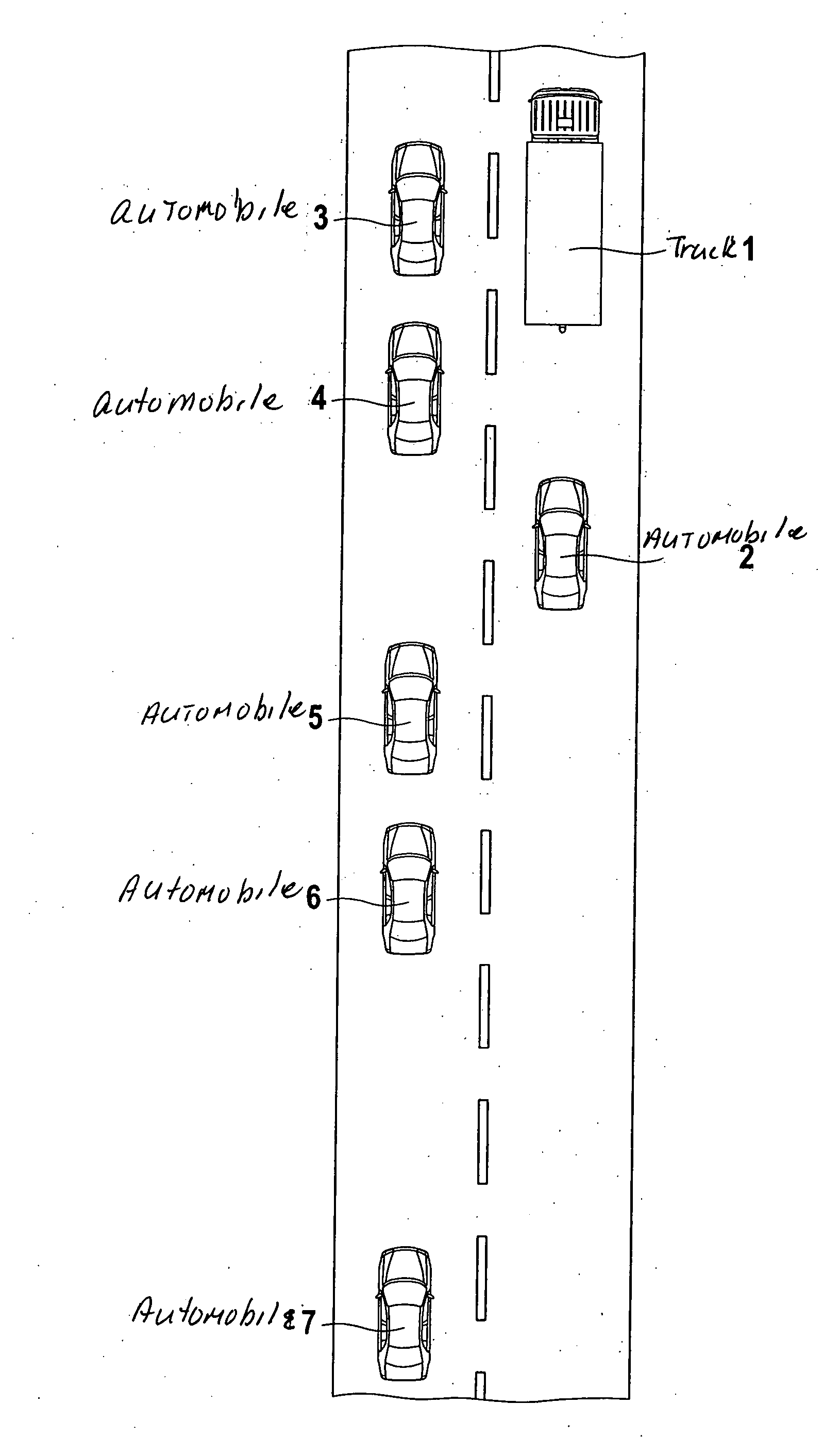
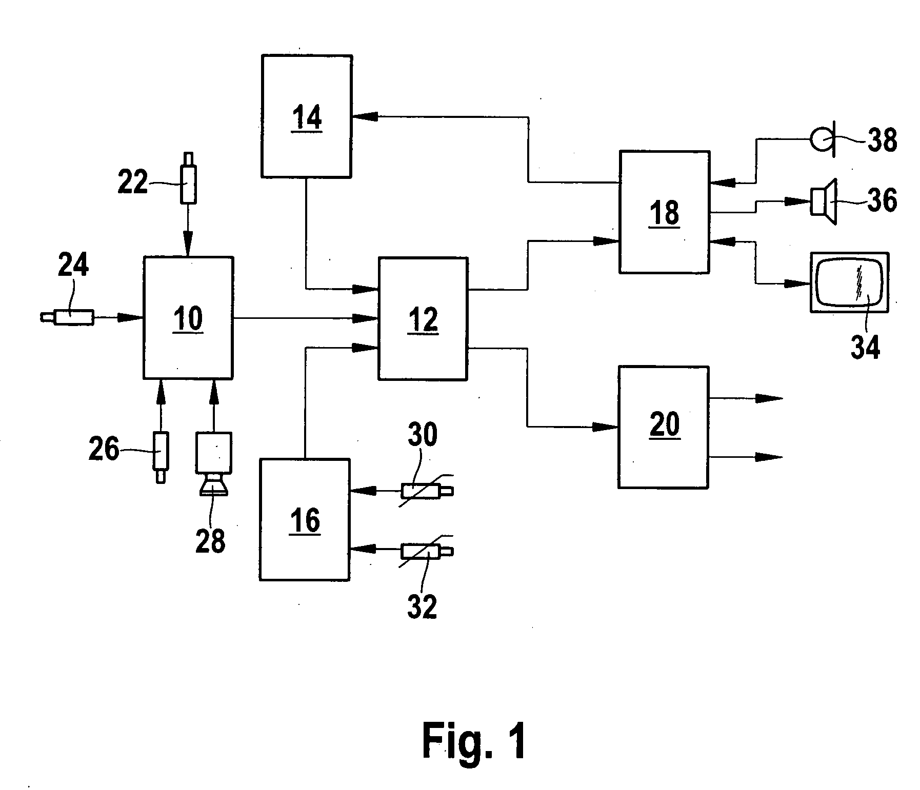
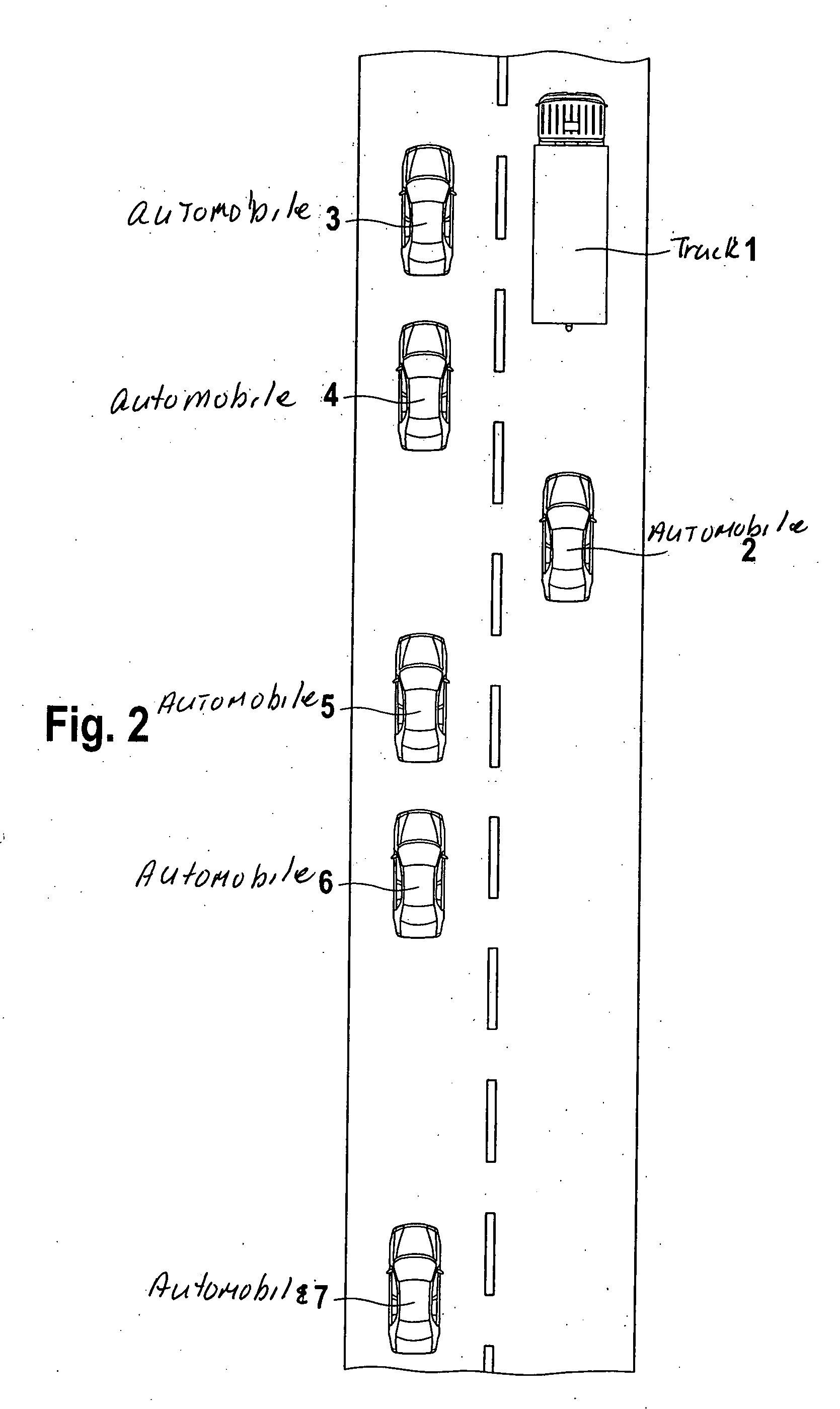
[0023]FIG. 1 shows a block diagram of the present invention, having a surround sensor system 10, an identification device 12, a setpoint-value memory 14, a dialog device 18, a control device 20 and an environmental sensor system 16. Surround sensor system 10 includes radar sensors 22, 24, 26 for dynamic distance measurement; from the distance and the time, it is possible to calculate the velocities and acceleration processes of the other motor vehicles or, in conjunction with the velocity of the host vehicle, it is possible to calculate the relative velocities of the other vehicles. Moreover, surround sensor system 10 may also contain a video camera 28 for recording the height and length of motor vehicles in conjunction with the distances ascertained by radar sensors 26, as well as for recording the color.

[0024]Setpoint values from the set including velocity, accelerating ability, driver reaction time and gap size are stored in setpoint-value memory 14. User profiles may also be sto...


PUM


Abstract

The gap indicator includes a surround sensor system for recording the traffic surround field including the traffic in at least one adjacent lane, an identification device for determining gaps in the traffic sufficient for a lane change, and a dialog device for the output of detailed driving instructions to the driver of the host motor vehicle.

Description

BACKGROUND INFORMATION[0001]In today's state of technological development, no assistance whatsoever is offered to the driver in monitoring the traffic to the rear. However, products such as blind-spot detection and “lane-change assistants” are being introduced into the market. However, in the case of the blind-spot detection, a type of red iris in the outside rearview mirror indicates only whether a vehicle is in the blind spot. In the case of the lane-change assistant, at the moment at which the driver signals or initiates the lane change, it is checked whether a vehicle is located or is approaching in the adjacent lane, and whether this could lead to a critical situation.[0002]In a known lane-change assistant, the desire by the driver to pass is recorded and taken into account, but the acceleration process is first initiated at a later time, namely, when the passing vehicle has moved away with a sufficient safety distance. In the event yet a further vehicle is following this passi...

Claims


Application Information

Patent Timeline
Patent Type & Authority Applications(United States)
IPC IPC(8): B60W30/08B60W10/18B60W30/16B60W40/10B60W50/08
CPCB60W10/06G01S2013/9357B60W30/08B60W30/16B60W30/18163B60W40/107B60W50/14B60W2050/146B60W2550/20B60W2550/306G01S13/87G01S13/931G01S2013/9332G01S2013/9353G08G1/16G01S13/867B60W10/184G08G1/167G01S2013/9315G01S2013/9322G01S2013/932B60W2554/00B60W2554/4041B60W2554/80
Inventor PLACKE, LARSBIESTER, LARS
Owner ROBERT BOSCH GMBH
Why Eureka
Try Eureka