Telescopic gun sight windage correction system
- Summary
- Abstract
- Description
- Claims
- Application Information
AI Technical Summary
Benefits of technology
Problems solved by technology
Method used
Image
Examples
Embodiment Construction
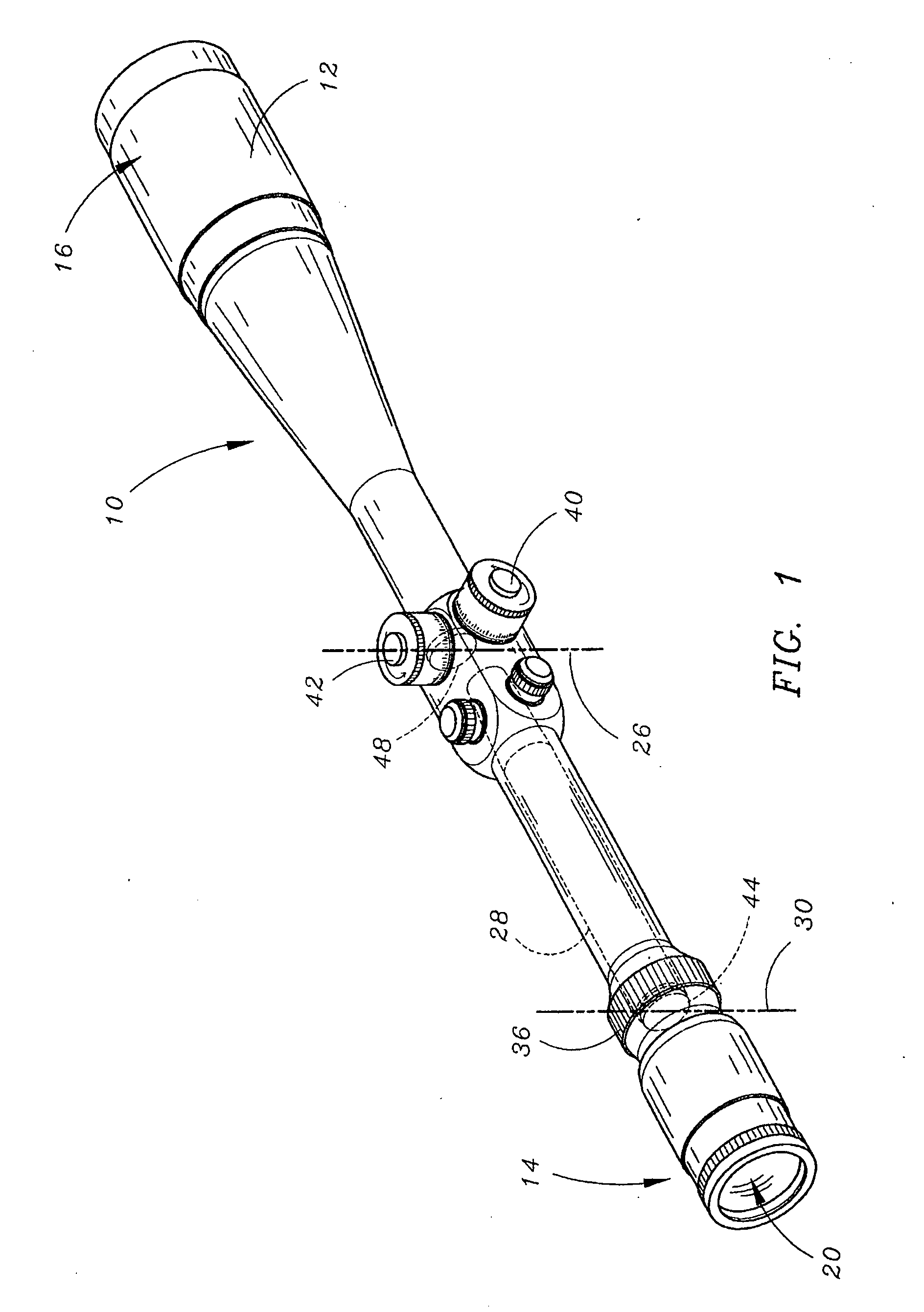
[0026]Referring to FIG. 1, the improved telescopic gun sight 10 is shown as including a pair of reticule adjustment knobs 40 and 42 disposed along the outside of the tubular housing 12 of the scope 10, for permitting the hunter to selectively adjust the effective position of a pair of sighting reticules disposed within the scope 10, in order to properly sight-in the rifle and correct for bullet drop and any crosswind.
[0027]The scope includes an eyepiece end 14 comprising an ocular lens system 20 through which the hunter views during siting of a target upon which he wishes to fire. The other end of the scope is the objective end 16 and includes an objective lens 22 which is directed toward the object to be viewed. The light rays coming from the object pass through objective lens 22 and converge to form an image on an image plane within the tubular housing and generally defined by reference numeral 26. Because the image appearing in the image plane will be the inverted image of the vi...
PUM
 Abstract
Description
Claims
Application Information
 - R&D
- Intellectual Property
- Life Sciences
- Materials
- Tech Scout
- Unparalleled Data Quality
- Higher Quality Content
- 60% Fewer Hallucinations
Browse by: Latest US Patents, China's latest patents, Technical Efficacy Thesaurus, Application Domain, Technology Topic, Popular Technical Reports.
© 2025 PatSnap. All rights reserved.Legal|Privacy policy|Modern Slavery Act Transparency Statement|Sitemap|About US| Contact US: help@patsnap.com


