Controller of exhaust gas purifying agent and exhaust gas purifying system

a technology of purifying agent and controller, which is applied in the direction of exhaust treatment electric control, machines/engines, instruments, etc., can solve the problems of difficult to obtain the optimum purifying agent quantity from those parameters, and achieve the effect of high purifying rate, high degree of accuracy and convenient handling

Inactive Publication Date: 2008-08-28
DENSO CORP
View PDF8 Cites 17 Cited by
  • Summary
  • Abstract
  • Description
  • Claims
  • Application Information

AI Technical Summary

Benefits of technology

[0025]It is possible, on the basis of each detection value to carry out data analysis and failure diagnosis, and to control a purifying agent quantity to an optimum value with a high degree of accuracy.
[0026]When the practicability of the above invention is considered in view of the demand from society (public interest), as represented by the aforementioned urea SCR (Selective Catalytic Reduction) system, a NOx purifying device that uses a urea aqueous solution (urea water) as an additive is expected as an exhaust gas purifying system to purify NOx (nitrogen oxide) in an exhaust gas at a high purifying rate. The reason why NH3 is added in the form of a urea aqueous solution is that a urea aqueous solution is easier to handle (less poisonous) than NH3. Consequently, considering the practicability of the current situation, it is effective to configure a controller such that the specific component is NOx and the purifying agent is NH3 produced by being added in the form of a urea aqueous solution and decomposing in an exhaust gas. Further, when such a urea SCR system is adopted in an automobile and a controller is mounted on a vehicle or the like having a diesel engine for example, it is possible to realize the improvement of fuel consumption and the reduction of PM while allowing NOx to be generated during combustion. This is a technology that largely contributes to the improvement in the performance of an automobile and the cleaning of an exhaust gas that is a key to the prevalence of diesel engines.

Problems solved by technology

Consequently, it is difficult to obtain an optimum purifying agent quantity from those parameters.

Method used


Image

  • Controller of exhaust gas purifying agent and exhaust gas purifying system
  • Controller of exhaust gas purifying agent and exhaust gas purifying system
  • Controller of exhaust gas purifying agent and exhaust gas purifying system

Examples


Embodiment Construction

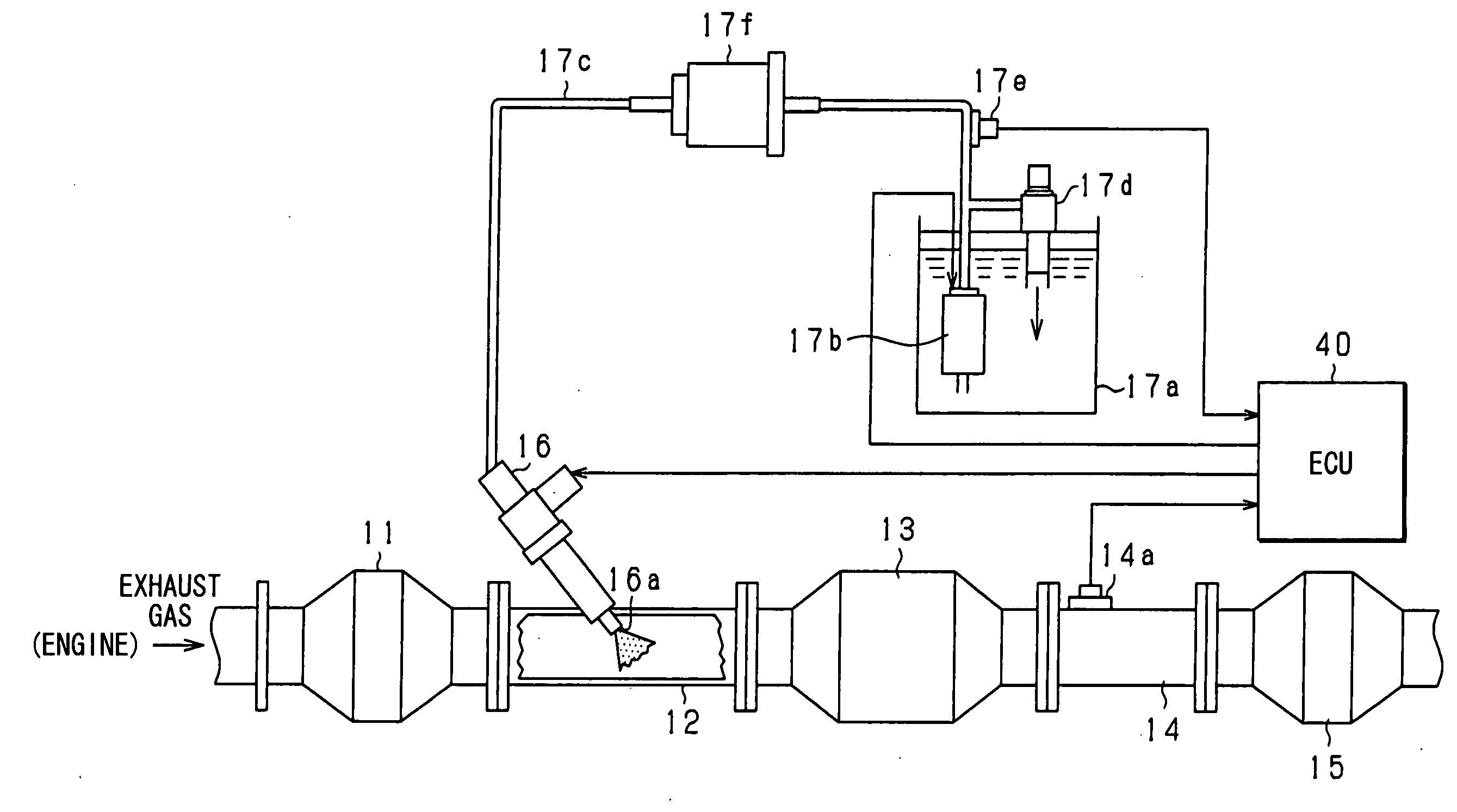
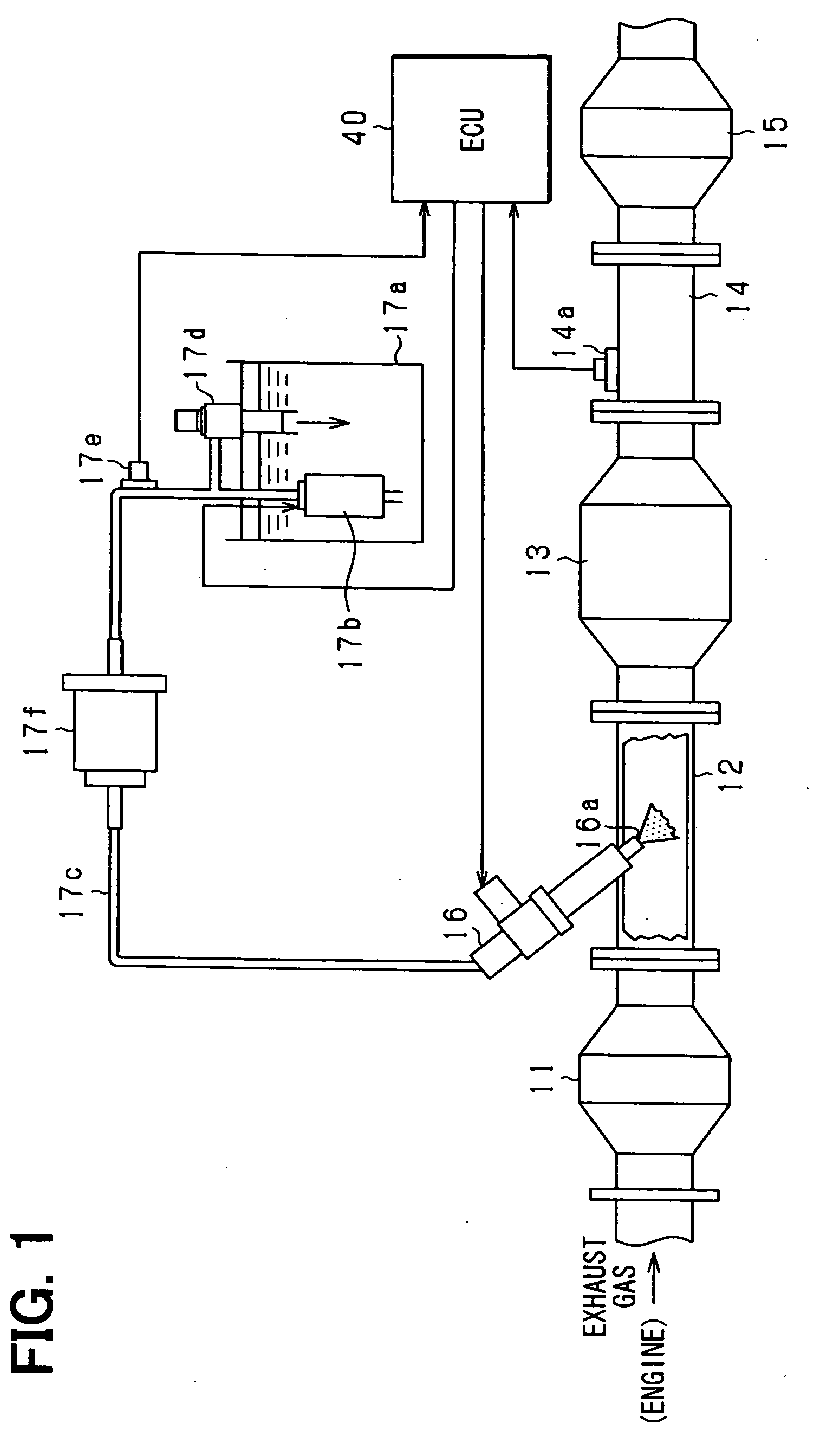
[0033]An embodiment of the present invention is hereunder explained in reference to drawings. The basic configuration of the exhaust gas purifying system in the embodiment conforms to that of an ordinary urea Selective Catalytic Reduction (SCR) system that has been stated earlier. A shown in FIG. 1, NOx in an exhaust gas is reduced (purified) by NH3 (ammonia) produced from a urea ((NH2)2CO) aqueous solution (hereunder referred to as urea water).

[0034]The configuration of the exhaust gas purifying system is described in detail in reference to FIG. 1.

[0035]FIG. 1 is a configuration diagram showing the outline of a urea SCR system (an exhaust gas purifying device) according to the present embodiment.

[0036]As shown in FIG. 1, such a system purifies an exhaust gas discharged from a reciprocal diesel engine (an exhaust gas source) mounted on a four-wheeled automobile (not shown in the figure) for example. The system includes various kinds of actuators to purify the exhaust gas, various ki...


PUM


Abstract

A quantity of a purifying agent that is added into an exhaust gas, reacts with a specific component in the exhaust gas, and purifies the exhaust gas is controlled. A controller is configured so as to be provided with a program to carry out either increment control for increasing the quantity of urea water sequentially or decrement control for decreasing the quantity of the urea water sequentially while monitoring, in NOx in the exhaust gas, the quantity not purified through the reaction with NH3 (the discharged NOx quantity); and switch the quantity control from the currently adopted increment or decrement control to the other increment or decrement control in response to whether the feature of the change of the discharged NOx quantity comes to a predetermined feature.

Description

CROSS-REFERENCE TO RELATED APPLICATION[0001]This application is based on Japanese Patent Application No. 2007-46062 filed on Feb. 26, 2007, the disclosure of which is incorporated herein by reference.FIELD OF THE INVENTION[0002]The present invention relates to an exhaust gas purifying agent controller to control a quantity of a purifying agent, for example ammonia (NH3) added in the form of a urea aqueous solution or the like, to purify an exhaust gas by reacting with a specific component, for example nitrogen oxide (NOx) or the like, in the exhaust gas. The present invention also relates to an exhaust gas purifying system to purify an exhaust gas by activating exhaust gas purifying reaction with a predetermined purifying agent on a catalyst as represented by a urea Selective Catalytic Reduction (SCR) system.BACKGROUND OF THE INVENTION[0003]In power plants, various kinds of factories, automobiles, and others, a urea SCR system has been being developed. In the case of an automobile (...

Claims


Application Information

Patent Timeline
Patent Type & Authority Applications(United States)
IPC IPC(8): F01N11/00F01N3/029F01N3/18
CPCF01N3/2066F01N11/00Y02T10/24Y02T10/47F01N2610/02Y02T10/12Y02T10/40
Inventor ICHIKAWA, ATARU
Owner DENSO CORP
Why Eureka
Try Eureka