Fastening structure for combining heat conducting pipe and fins

a technology of heat conducting pipe and fastening structure, which is applied in the direction of indirect heat exchangers, semiconductor/solid-state device details, lighting and heating apparatus, etc., can solve the problems of increasing the effect so as to improve the combination situation of the heat conducting pipe and the fins, the effect of increasing the efficiency of heat conduction and reducing the resistance of working fluid in the heat conducting pip

Inactive Publication Date: 2008-08-28
CHEN SHYH MING
View PDF5 Cites 13 Cited by
  • Summary
  • Abstract
  • Description
  • Claims
  • Application Information

AI Technical Summary

Benefits of technology

[0006]According to the above-mentioned technical solution, the present invention provides a fastening structure for combining a heat conducting pipe and a plurality of fins. Comparing to the conventional shaping method, the method of the invention can improve the combination situation of the heat conducting pipe and the fins. Furthermore, the indentation portions are formed on the connection positions of the surface of the heat conducting pipe in the through slot. With a dotted and discontinuous distribution, the indentation portions can effectively compress the heat conducting pipe to be deformed and thus be combined tightly with the through holes. Accordingly, the resistance of the working fluid in the heat conducting pipe is reduced, and the efficiency of the heat conduction is increased.

Problems solved by technology

Except for providing a more firmly fastening structure, the indentation portions can, due to their dotted and discontinues distribution, further reduce the resistance of the working fluid in the heat conducting pipe and increase the effect of heat conduction.

Method used


Image

  • Fastening structure for combining heat conducting pipe and fins
  • Fastening structure for combining heat conducting pipe and fins
  • Fastening structure for combining heat conducting pipe and fins

Examples


Embodiment Construction

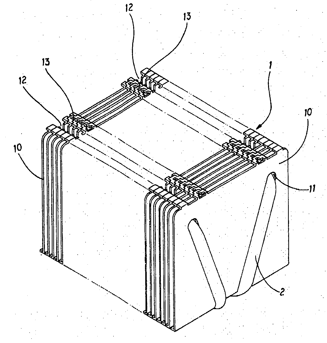
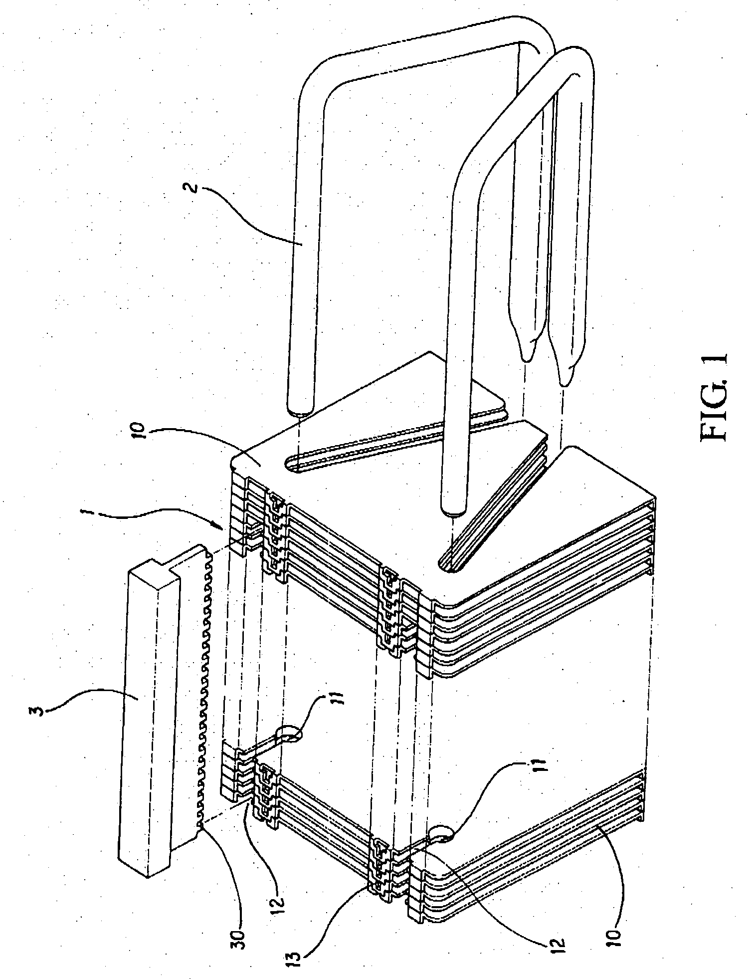
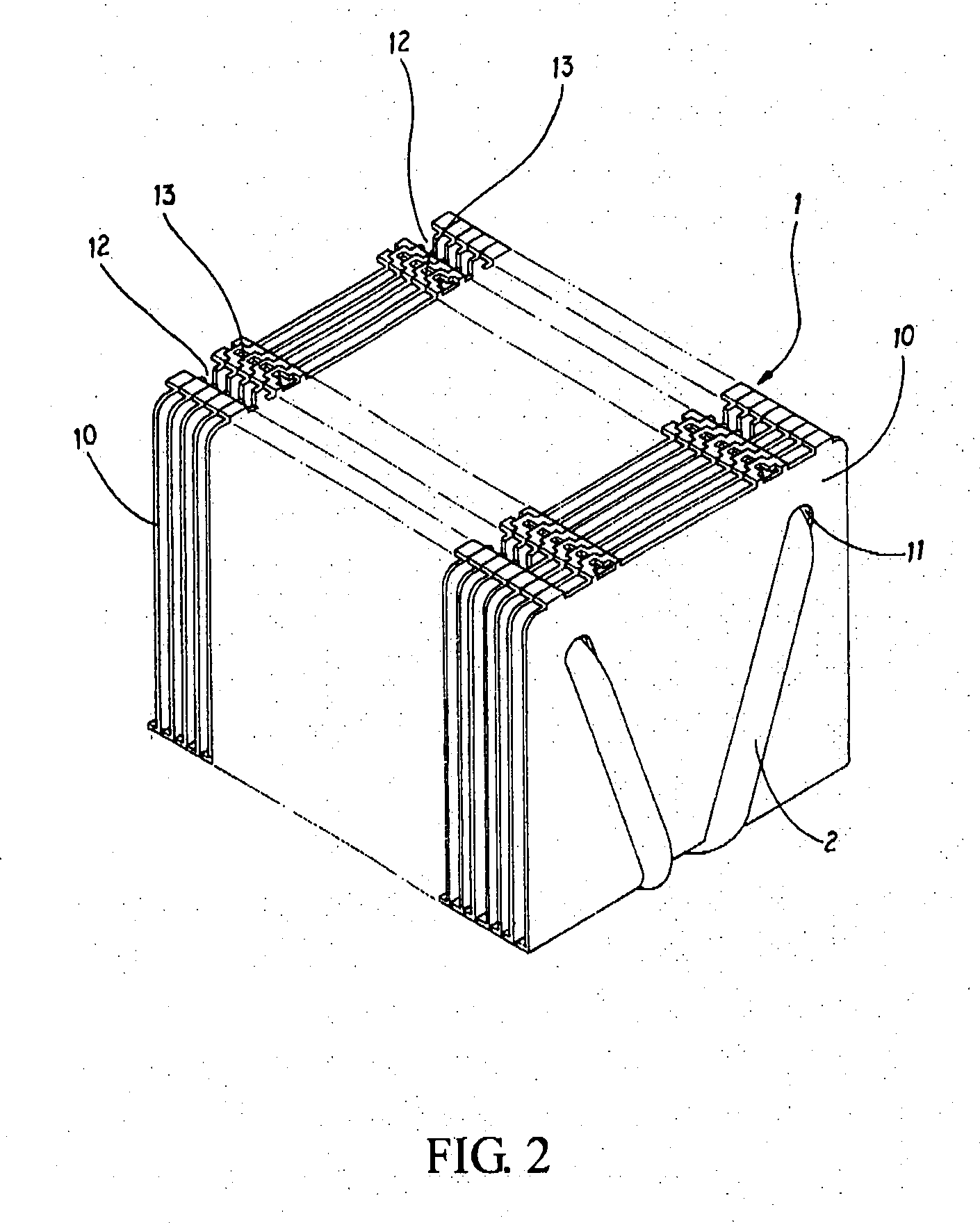
[0015]Please refer to FIGS. 1-3. A fastening structure for combining a heat conducting pipe and fins according to the present invention is schematically illustrated, wherein the cooler 1 includes a plurality of fins 10. There is at least one through hole 11 and a through slot 12 connected to the through hole 11 formed on the surface of each of the fins. Fasteners 13 are further mounted on both lateral sides of each of the fins 10. At least a heat conducting pipe 2 is penetratingly disposed within the through holes 11 of the fins 10. A mold pressing component 3 is allowed to pass through the through slots 12. The end portion of the mold pressing component 3 includes a plurality of drifts 30 capable of stamping the connection positions on the surface of the heat conducting pipe 2 for shaping the indentation portions 20. Furthermore, the distance between two adjacent drifts 30 corresponds to the distance between two adjacent fins 10. According to the above-mentioned structures, the fin...


PUM


Abstract

A fastening structure of a heat conducting pipe and a plurality of fins is provided in a cooler containing a plurality of fins. Each of the surfaces of the fins includes at least a through hole and a through slot connecting to the through hole. The heat conducting pipe penetrates through the through holes of the fins. The drifts located at the end portion of the mold pressing piece are allowed to pass through the through slots to stamp the connection positions on surface of the heat conducting pipe for shaping the indentation portions. The indentation portions compress the heat conducting pipe to be combined tightly with the through holes so that the fins and the heat conducting pipe are combined tightly for strengthening the combination of the fins and the heat conducting pipe effectively, and preventing the heat conducting pipe from being damaged so as to raise the quality and heat conductivity of the products.

Description

FIELD OF THE INVENTION[0001]The present invention relates to a fastening structure of a heat conducting pipe and fins, and particularly relates to a fastening structure of a heat conducting pipe and fins of a cooler applied in an Integrated Circuit (IC) or an electric element. An important feature of the fastening structure is to form a through hole on each of the fins, and a through slot connecting to the through hole. Furthermore, by allowing the mold pressing component to penetrate through the through slots, indentation portions that compress the heat conducting pipe to combine tightly with the through holes are stamped and formed at the connection positions on the surface of the heat conducting pipe in the through slot, thereby achieving a tight effect of the product.BACKGROUND OF THE INVENTION[0002]Conventionally, to combine a heat conducting pipe and the fins, a layer of solder needs to be coated on the junction surface between the heat conducting pipe and the fins. The heat c...

Claims


Application Information

Patent Timeline
Patent Type & Authority Applications(United States)
IPC IPC(8): H05K7/20
CPCF28D15/0266F28F1/30F28F2275/085H01L23/3672H01L23/4093H01L2924/0002H01L23/427H01L23/467H01L2924/00F28D15/0275
Inventor CHEN, SHYH-MING
Owner CHEN SHYH MING
Why Eureka
Try Eureka