

Plasma processing apparatus
a processing apparatus and plasma technology, applied in the direction of plasma technique, coating, electric discharge lamps, etc., can solve the problems of insufficient consideration of the attainable temperature range in these conventional methods, further absorbing heat from the heater, and difficult control of the heater actuation. to achieve the effect of improving process efficiency
- Summary
- Abstract
- Description
- Claims
- Application Information
AI Technical Summary
Benefits of technology
Problems solved by technology
Method used
Image

Examples
embodiment 1
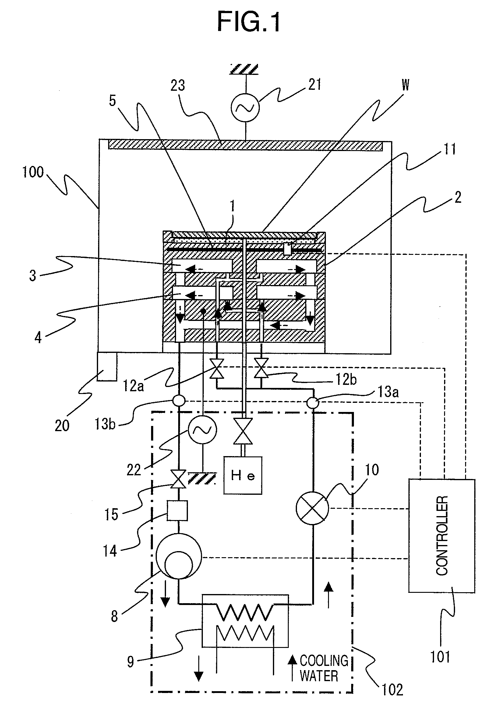
[0028]A first embodiment of this invention will be described in detail in reference to FIG. 1, FIGS. 2A through 2C, and FIG. 5. FIG. 1 schematically shows the entire structure of a plasma processing apparatus as a first embodiment of this invention. FIGS. 2A through 2C schematically show in cross sections the structure of the sample stage used in the embodiment shown in FIG. 1. FIG. 5 graphically shows the changes with time of various quantities or states, observed in the operation of the plasma processing apparatus shown in FIG. 1.
[0029]As shown in FIG. 1, the plasma processing apparatus as the first embodiment of this invention is divided into such main sections as a processing chamber 100 placed in a vacuum vessel, a sample stage 2 located at the central bottom position within the processing chamber 100, a cooling circuit 102 for feeding refrigerant to the sample stage 2 so as to control the temperature of the sample stage 2, and a controller 101 for controlling the operations of...
modification 1
[Modification 1]
[0071]FIGS. 3A and 3B show a first modification of the embodiment of this invention. FIG. 3A shows in horizontal cross section the structure of a modified sample stage for the plasma processing apparatus shown in FIG. 1.
[0072]As shown in FIG. 3A, the modified sample stage has the internal of its top member 25′ so cut as to define main refrigerant ducts 3′ and auxiliary refrigerant ducts 4′ approximately at the same vertical level, the ducts 3′ and 4′ having the horizontal cross section of a narrow sector. The grooves radially arranged from the central axis toward the periphery, of the sample stage and serving as the main refrigerant ducts 3′ are alternated with the grooves radially arranged from the central axis toward the periphery, of the sample stage and serving as the auxiliary refrigerant ducts 4′.
[0073]In this modified embodiment, the heat transfer area of each auxiliary duct 4′ is made smaller than that of each main duct 3′, that is, the central angle of secto...
embodiment 2
[0076]A second modification of the embodiment shown in FIG. 1 will be described below with reference to FIGS. 4A and 4B. FIG. 4A schematically shows in horizontal cross section the structure of the sample stage used in a plasma processing apparatus as another embodiment of this invention.
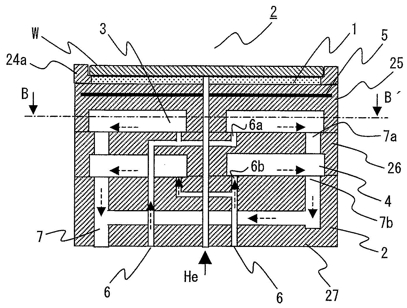
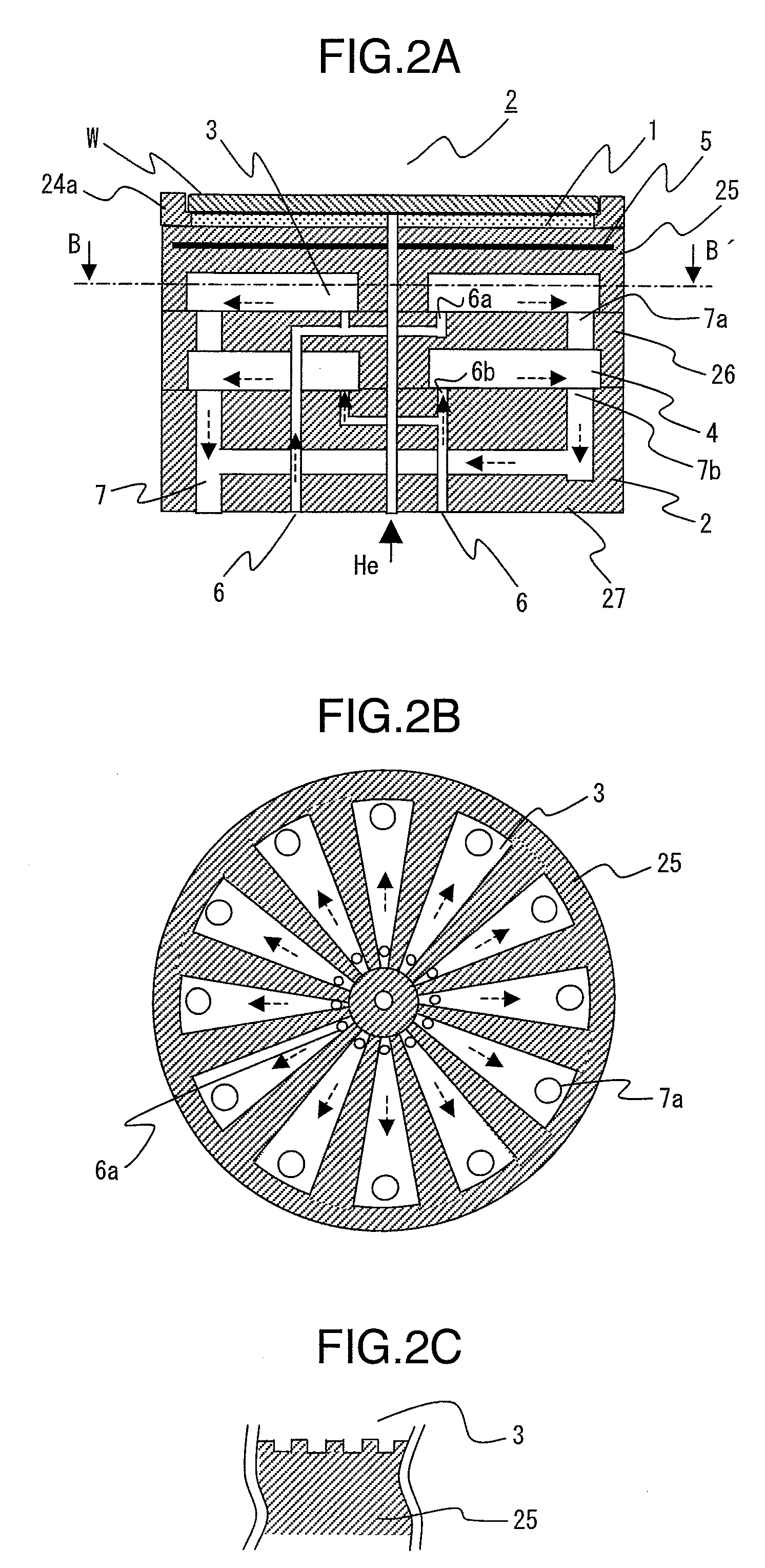
[0077]As shown in FIGS. 2A and 2B, a main refrigerant duct 3 and an auxiliary refrigerant duct 4 are provided in a single groove so that the heat transfer area of each groove varies depending on the change in the amount of refrigerant flow through the groove. The main refrigerant ducts 3 are cut in the internal of the top member 25 of the sample stage, arranged radially from the central axis of the stage toward the periphery of the stage, and each duct 3 has the horizontal cross section of a narrow sector. Each of the auxiliary refrigerant ducts 4, having the horizontal cross section of a narrower sector, is cut in the bottom surface of each main duct 3. FIG. 2B is a vertical cross section along the...
PUM
| Property | Measurement | Unit |
|---|---|---|
| Temperature | aaaaa | aaaaa |
| Distance | aaaaa | aaaaa |
| Heat | aaaaa | aaaaa |
Abstract
Description
Claims
Application Information