Digital current sense

Inactive Publication Date: 2008-08-28
INFINEON TECH AMERICAS
View PDF11 Cites 36 Cited by
  • Summary
  • Abstract
  • Description
  • Claims
  • Application Information

AI Technical Summary

Benefits of technology

[0015]It is an object of the present invention to provide a circuit for calculating the current through an inductor using DCR or resistor sensing, the cir

Problems solved by technology

Measuring the current in an inductor is a problem typically encountered in switching power supplies.
However, minimizing the power dissipation limits the available signal for current sensing.
Disadvantages of the above approach include additional power being dissipated in the resistive sense element thereby reducing the overall efficiency of the switching converter and a need fo

Method used


Image

  • Digital current sense
  • Digital current sense
  • Digital current sense

Examples


Embodiment Construction

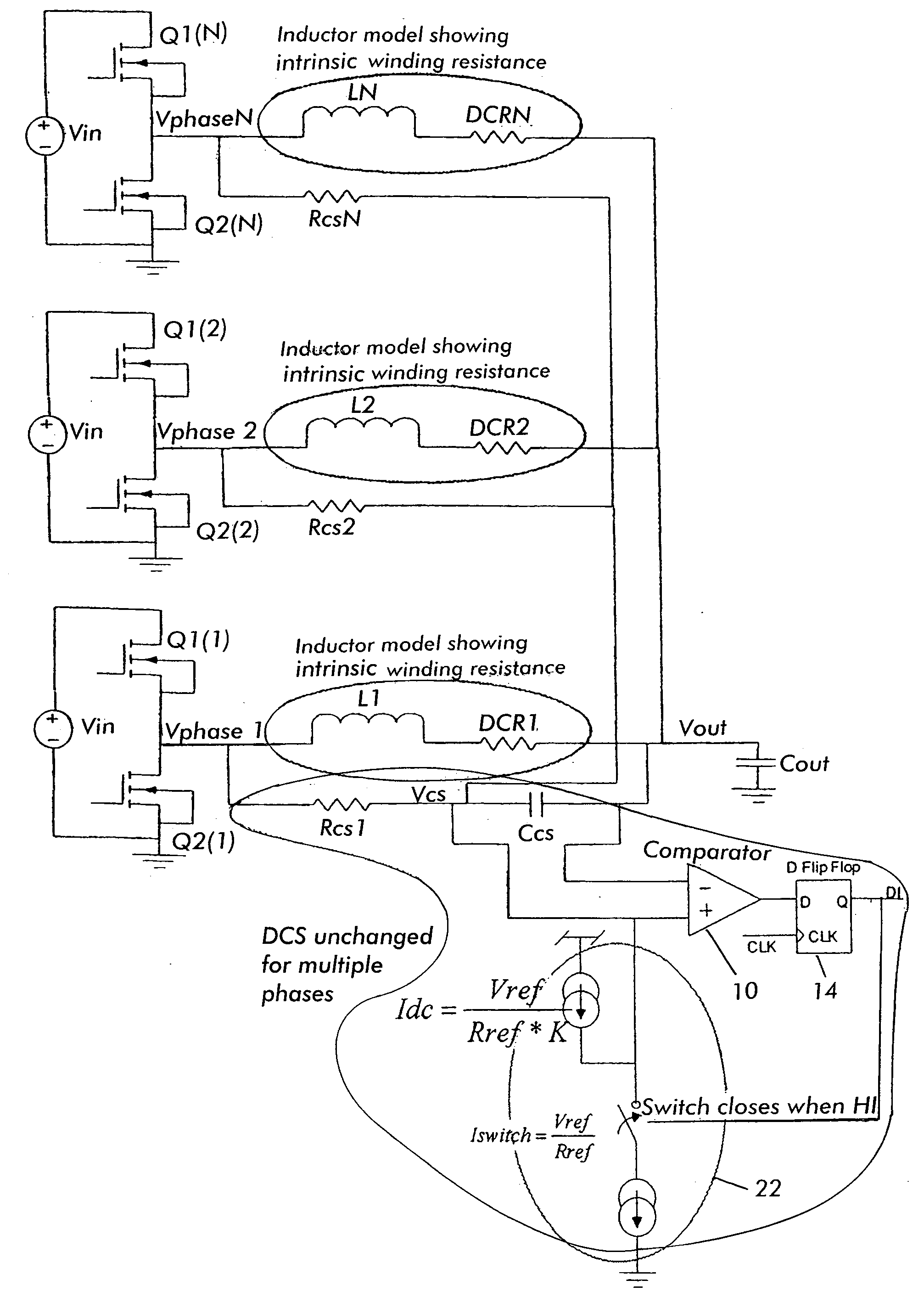
[0031]One embodiment of the present invention is illustrated in FIG. 4, where a DCS circuit 5 is shown. To assure correct operation of this embodiment positive inductor current must be maintained. The circuit 5 includes a comparator 10, and a switched current source Iswitched 12, and a filter comprising a resistor RCS and a capacitor CCS. The switched current source 12 can be any circuit which sinks an average output current that increases with the increasing duty cycle D, and can supply a sufficient amount of an average current to cancel the average current flowing through the resistor RCS. The comparator 10 can be clocked by a D Flip-Flop 14 placed in series with or asynchronous to the output of the comparator 10. Using a clocked comparator 10 has the advantage that the switching frequency of the DCS circuit 5 can be controlled without hysteresis or knowledge of the frequency components of the inductor current Iinductor. The circuit 5 forms a portion of a delta-sigma analog to dig...


PUM


Abstract

A circuit for measuring a current in an output inductor of at least one switching power supply having high- and low-side switches connected at a switching node, the output inductor having input and output terminals, the input terminal being connected to the switching node. The circuit including a sensing circuit for detecting a direction of current through the inductor, the sensing circuit generating a sense voltage related to the direction of current; a comparator circuit having an output terminal and input terminals coupled to the sensing circuit and receiving the sense voltage, the comparator circuit providing a comparison output of the sense voltage and an output voltage of the output inductor; and a switched current source circuit controlled by the comparison output for providing a reference current to the sensing circuit, the comparison output turning the switched current source circuit ON and OFF depending on the comparison output and having a duty cycle, whereby the average current flowing through the switched current source circuit is substantially equal to the average current in the sensing circuit and proportional to the duty cycle, the duty cycle being proportional to the inductor current.

Description

CROSS-REFERENCE TO RELATED APPLICATION[0001]This application is based on and claims priority to U.S. Provisional Patent Application Ser. No. 60 / 891,586, filed on Feb. 26, 2007 and entitled DIGITAL CURRENT SENSE, the entire contents of which is hereby incorporated by reference.BACKGROUND OF THE INVENTION[0002]The present invention relates to measuring the current through an inductor and more particularly to generating analog and digital measurements.[0003]Digital Current Sense (DCS) is a method for measuring the current through an inductor. DCS derives a continuous steam of digital indicators, i.e., ones and zeros, in which the information about the current is embedded as the ratio of ones to zeros. A digital representation of an average current in the inductor can be achieved by simply counting the ones present within a specified averaging interval.[0004]Several simple methods for generating an analog representation of the inductor current are known. The analog signal can be easily ...

Claims


Application Information

Patent Timeline
IPC IPC(8): G01R19/00
CPCH02M3/1588Y02B70/1466H02M2001/0009H02M1/0009Y02B70/10
Inventor FORAN, RYANKROEGER, RICHARD
Owner INFINEON TECH AMERICAS
Why Eureka
Try Eureka