Capacitive sensor

a capacitive sensor and sensor technology, applied in capacitance measurement, resistance/reactance/impedence, instruments, etc., can solve the problems of amplitude fluctuations, labor-intensive and costly circuit engineering, and inability to compare the difference of current voltage-convert currents,

Inactive Publication Date: 2008-08-28
IMF ELECTRONIC GMBH
View PDF4 Cites 7 Cited by
  • Summary
  • Abstract
  • Description
  • Claims
  • Application Information

AI Technical Summary

Benefits of technology

[0012]The capacitive sensor according to the invention, in which the previously deduced and indicated object is achieved, is characterized first and essentially in that the reference impedance can be tuned. By this simple measure, the value of the reference impedance—and thus, also the capacitance of a reference impedance that is configured as a reference condenser—can be adjusted, in any desired state of influence of the capacitive sensor, to the impedance or capacitance of the measuring condenser that is tied to the state of influence. Because of the ability to make adjustments within the range of the actual capacitive sensor, no ability to make adjustments or to set a zero point within the analysis unit is needed, so that the analysis unit can be produced significantly more simply and economically in terms of circuit engineering.
[0033]In another advantageous configuration of the capacitive sensor according to the invention, the measuring condenser is connected via an electrical line to the current supply network, such that the electrical line and the measuring condenser form a resonator, whereby the electrical line is in particular a coaxial line and / or whereby the resonator in particular is a λ / 4 resonator. By this measure, in particular by the use of a coaxial line, resonance frequencies up to the megahertz and gigahertz range can be achieved in a simple way, whereby in this frequency range, the differentiation between an only slight adhesion of a medium to the sensor and the surrounding area of the sensor with a large volume of the medium—as described above—is especially very possible.

Problems solved by technology

The disadvantage to the above-described capacitive sensor is that the analysis of the current signals in the analysis unit is comparatively expensive.
In particular, the specification of a reference value, to which the difference of the current voltage-converted currents is compared, is labor-intensive and costly in terms of circuit engineering, and in addition, is prone to frequency and amplitude fluctuations of the alternating signal.
Also, it has been found that the known sensors, in the working frequency of 2 MHz indicated in the prior art, are not suitable to be used as fill-level sensors, since they then are not able to distinguish whether a medium fills a larger area of volume around the sensor or whether only a small adhesion of this medium to the sensor has been left after the medium has left the area of the capacitive sensor that is to be monitored; the fill level thus drops below the position of the capacitive sensor.

Method used


Image

  • Capacitive sensor
  • Capacitive sensor
  • Capacitive sensor

Examples


Embodiment Construction

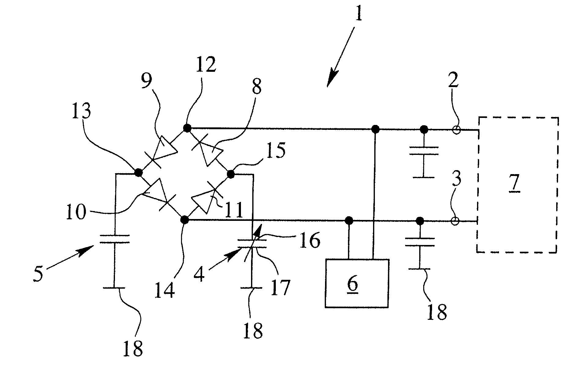
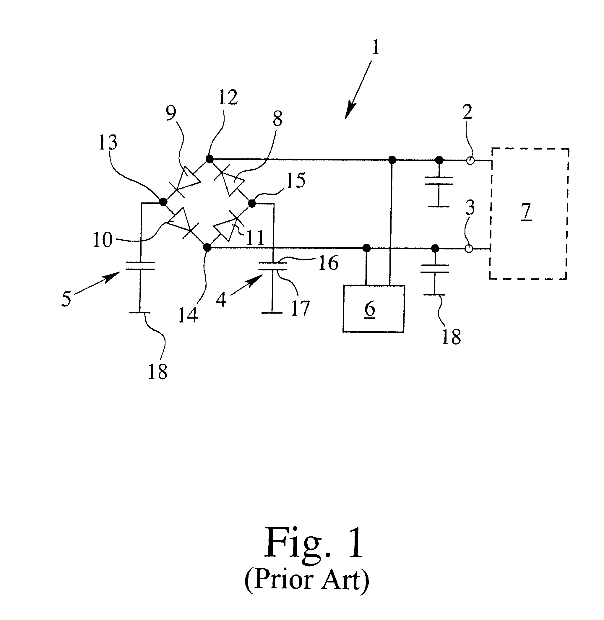
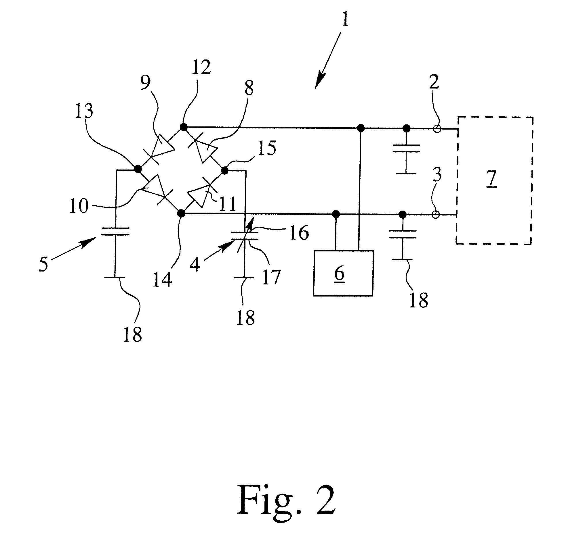
[0050]FIG. 1 shows a capacitive sensor 1, as it is known from the prior art. On a first connection 2 and a second connection 3, the capacitive sensor 1 has a reference impedance that is configured as a—non-tunable—reference condenser 4 and a measuring condenser 5, an electrical alternating signal source 6, an analysis unit 7, as well as a diode ring that consists of four diodes 8, 9, 10, 11 that are connected one behind the other in series and in the same direction. In the embodiments according to FIGS. 1 to 6, the reference impedance is always embodied as a reference condenser 4.

[0051]The diode ring has a first connection 12 between the first diode 8 and the second diode 9, a second connection 13 between the second diode 9 and the third diode 10, a third connection 14 between the third diode 10 and the fourth diode 11, and finally a fourth connection 15 between the fourth diode 11 and the first diode 8. The first electrode 16 of the reference condenser 4 is connected to the fourth ...


PUM


Abstract

A capacitive sensor with at least one reference impedance and at least one measuring condenser (5), with at least one electrical alternating signal source (6), with a current supply network as well as with an analysis unit (7) in which the reference impedance and the measuring condenser (5) are connected via the current supply network to the alternating signal source (6) and the analysis unit (7) in such a way that the charge and discharge currents of the reference impedance and the measuring condenser (5) can be analyzed—at least partially—by the analysis unit (7). The capacitive sensor avoids—at least partially—drawbacks in the known capacitive sensors in that the reference impedance can be tuned.

Description

BACKGROUND OF THE INVENTION[0001]1. Field of Invention[0002]The invention relates to a capacitive sensor with at least one reference impedance and at least one measuring condenser, with at least one electrical alternating signal source, with a current supply network as well as with an analysis unit, whereby the reference impedance and the measuring condenser are connected via the current supply network to the alternating signal source and the analysis unit in such a way that the charge and discharge currents of the reference impedance and the measuring condenser can be analyzed—at least partially—by the analysis unit. In particular, in this case, this can be a capacitive sensor with at least a first connection and a second connection, with at least one reference impedance and a measuring condenser, with at least one electrical alternating signal source, with an analysis unit as well as with a diode ring that consists of at least four diodes that are connected one behind the other in...

Claims


Application Information

Patent Timeline
Patent Type & Authority Applications(United States)
IPC IPC(8): G01R27/26
CPCG01R27/2605G01D5/24
Inventor GUNDLACH, JOCHENPALATA, JAROMIR
Owner IMF ELECTRONIC GMBH
Why Eureka
Try Eureka