Termination circuit, vehicle-mounted control apparatus, and vehicle-mounted communication system

a technology of communication system and terminal circuit, which is applied in the direction of ignition automatic control, electric controllers, instruments, etc., can solve the problems of reducing the amplitude of differential signals, imposing large restrictions on the length and layout of transmission lines, and reducing the accuracy of digitizing differential signals at the receiving side. , to achieve the effect of improving the signal transmission speed of differential signals and preserving the anti-noise

Inactive Publication Date: 2008-08-28
DENSO CORP
View PDF2 Cites 24 Cited by
  • Summary
  • Abstract
  • Description
  • Claims
  • Application Information

AI Technical Summary

Benefits of technology

[0029]According to the present invention, it is possible to provide a termination circuit that can improve a signal transmission speed of a differential signal, and to ensure a good waveform of the differential signal without sacrificing its anti-noise effect, and to provide a vehicle-mounted control apparatus and a vehicle-mounted communication system each including such a termination circuit.

Problems solved by technology

The reduction of the amplitude of a differential signal not only lowers the accuracy of digitizing the differential signal at a receiving side, but also imposes a large restriction on the length and layout of the transmission line.
However, this lowers the anti-noise effect described above.
As explained above, ensurement of a necessary value of the amplitude of a differential signal, and improvement of a signal transmission speed of a transmission line are in a trade-off relationship, and hence it is difficult to satisfy both of them.

Method used


Image

  • Termination circuit, vehicle-mounted control apparatus, and vehicle-mounted communication system
  • Termination circuit, vehicle-mounted control apparatus, and vehicle-mounted communication system
  • Termination circuit, vehicle-mounted control apparatus, and vehicle-mounted communication system

Examples


Embodiment Construction

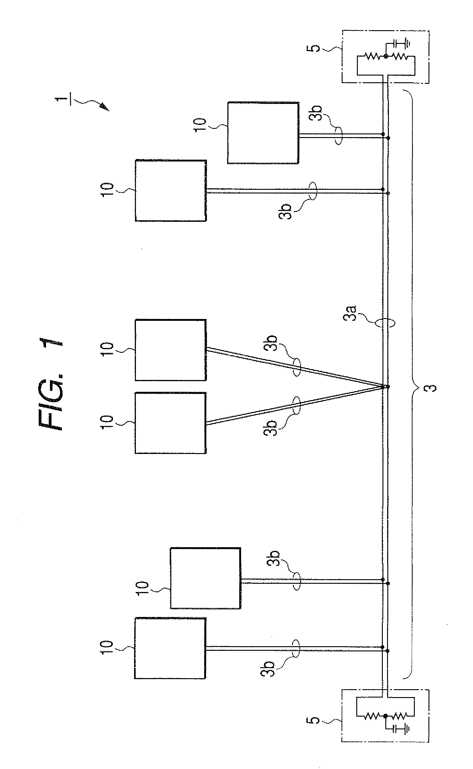
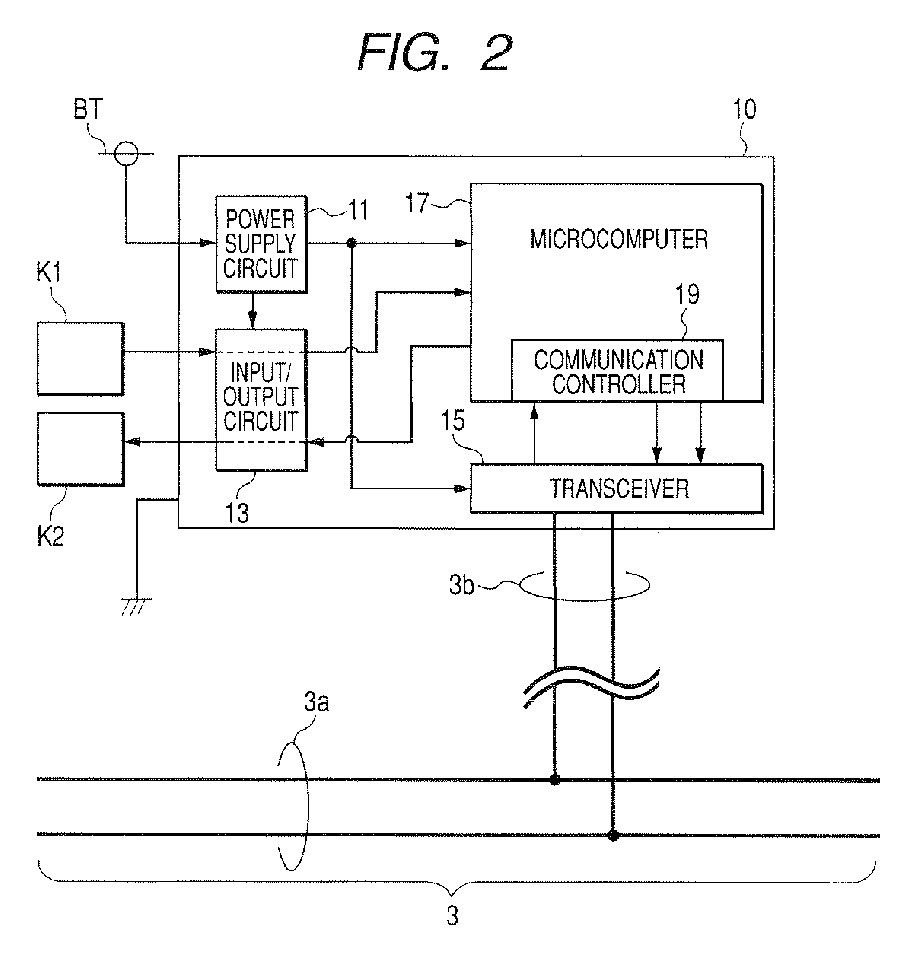
[0051]FIG. 1 is a diagram schematically showing an overall structure of a vehicle-mounted communication system 1 according to an embodiment of the invention. The vehicle-mounted communication system 1 includes a transmission line 3 constituting a LAN, and a plurality of vehicle-mounted control apparatuses 10 connected to the transmission line 3.

[0052]The transmission line 3, which has a bus-like configuration, includes a trunk line 3a and branch lines 3b branching from the trunk line 3a. Each vehicle-mounted control apparatuses 10 is connected to an end of a corresponding one of the branch lines 3b. The transmission line 3 is constituted by a twist-pair line formed by a pair of signal wires twisted together.

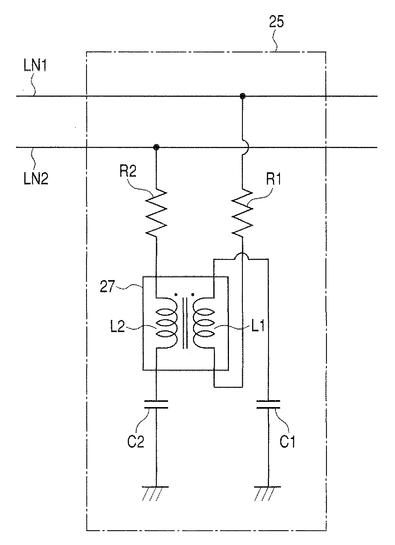
[0053]The transmission line 3 is connected with a termination circuit 5 at each of the open ends thereof. The termination circuit 5 is a split termination circuit constituted by a pair of resistive elements having the same resistance and connected in series between the pair of th...


PUM


Abstract

The termination circuit for use in a transmission line to transmit a differential signal includes a first series circuit of a resistive element and an inductive element connected between one of two signal wires of the transmission line and a reference potential, and a second series circuit of a resistive element and an inductive element connected between the other of the signal wires and the reference potential. The inductive elements of the first and second series circuits are magnetically coupled such that they generate magnetic fields having such directions as to reinforce each other when a common-mode signal flows along the transmission line, and generate magnetic fields having such directions as to weaken each other when a differential-mode signal flows along the transmission line.

Description

CROSS-REFERENCE TO RELATED APPLICATION[0001]This application is related to Japanese Patent Application No. 2007-49556 filed on Feb. 28, 2007, the contents of which are hereby incorporated by reference.BACKGROUND OF THE INVENTION[0002]1. Field of the Invention[0003]The present invention relates to a termination circuit used in a transmission line constituted by a pair of signal wires for transmitting a differential signal, a vehicle-mounted control apparatus, and a vehicle-mounted communication system including the termination circuit and the vehicle-mounted control apparatus.[0004]2. Description of Related Art[0005]Generally, as shown in FIG. 18A, in a communication system in which a plurality of terminal apparatuses 110 are connected to a transmission line LN having a bus-like configuration or a star-like configuration, a termination circuit 100 is connected to each of the open ends of the transmission line LN to prevent signal reflection at the open ends.[0006]It has been known to...

Claims


Application Information

Patent Timeline
Patent Type & Authority Applications(United States)
IPC IPC(8): H01P1/24
CPCH04B3/30
Inventor SAKAI, NAOTOKONDOH, KOUJI
Owner DENSO CORP
Why Eureka
Try Eureka