UWB Receiver scaling clock frequency by data rate and data reception method thereof

a data rate and receiver technology, applied in the field of radio transmitter receiver systems, can solve the problems of static power consumption, receiver may dissipate a relatively large amount of power, and the uwm system under fcc regulation may have relatively minor interference problems, so as to minimize power consumption for bit-level processing operations

Active Publication Date: 2008-08-28
SAMSUNG ELECTRONICS CO LTD
View PDF6 Cites 15 Cited by
  • Summary
  • Abstract
  • Description
  • Claims
  • Application Information

AI Technical Summary

Benefits of technology

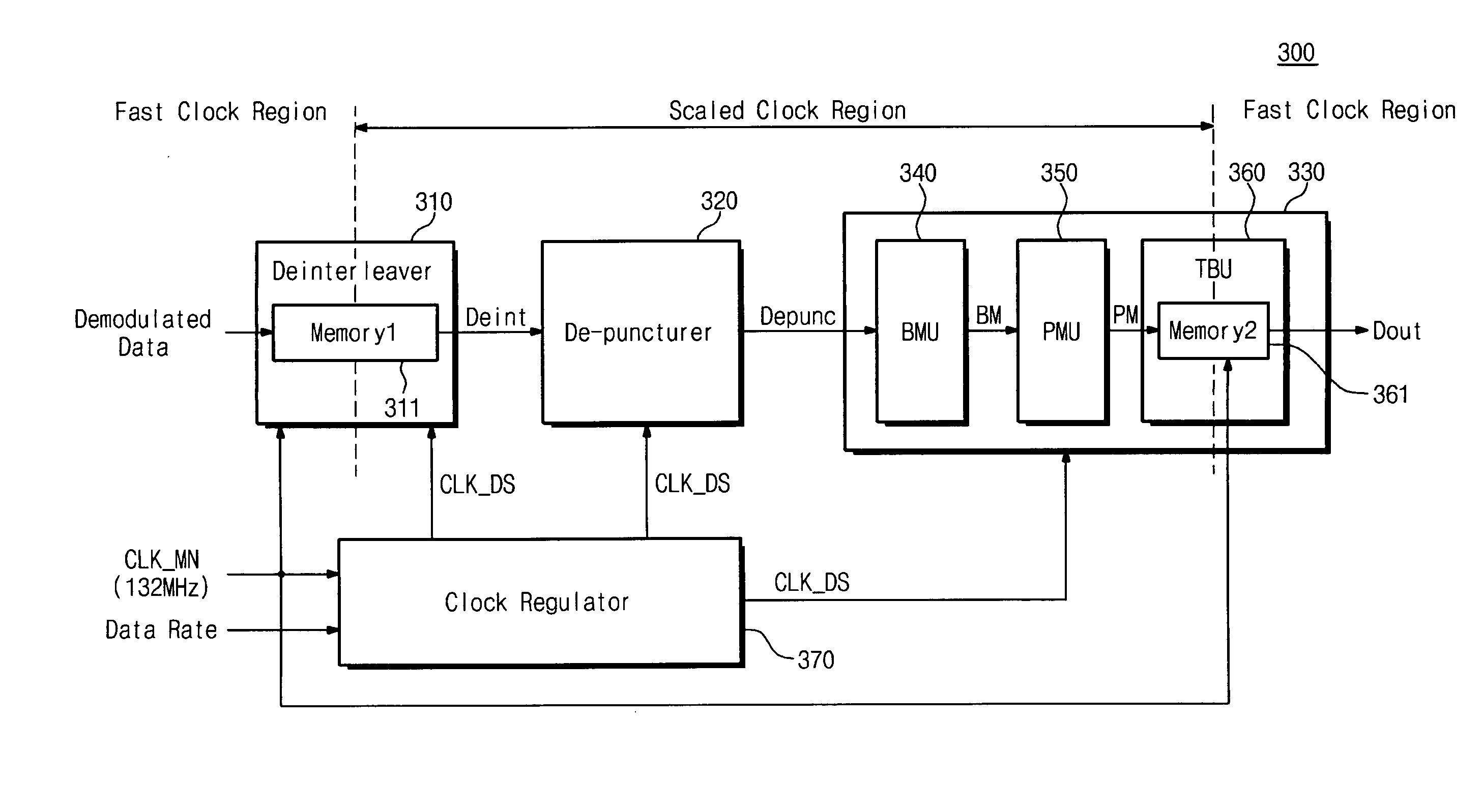
[0015]Example embodiments of the present application may reduce static power consumption caused by the fixed clock frequency of the traditional receiver.
[0021]In accordance with example embodiment of the present application, the scaled clock may not be interrupted, thereby minimizing power consumption for bit-level processing operation.

Problems solved by technology

Because a conventional UWB system generally uses an ultrahigh bandwidth, interference with radio frequencies used in a global positioning system (GPS) and mobile communication networks may cause problems.
Due to the low power spectral density, the UWM system under FCC regulation may have relatively minor interference problems with other communication signals.
Because the receiver may require a high clock frequency for supporting the fast data transmission rate, the receiver may dissipate a relatively high amount of power.
During an idle time of the bit level processing unit, static power consumption may remain due to leakage currents of clock paths.
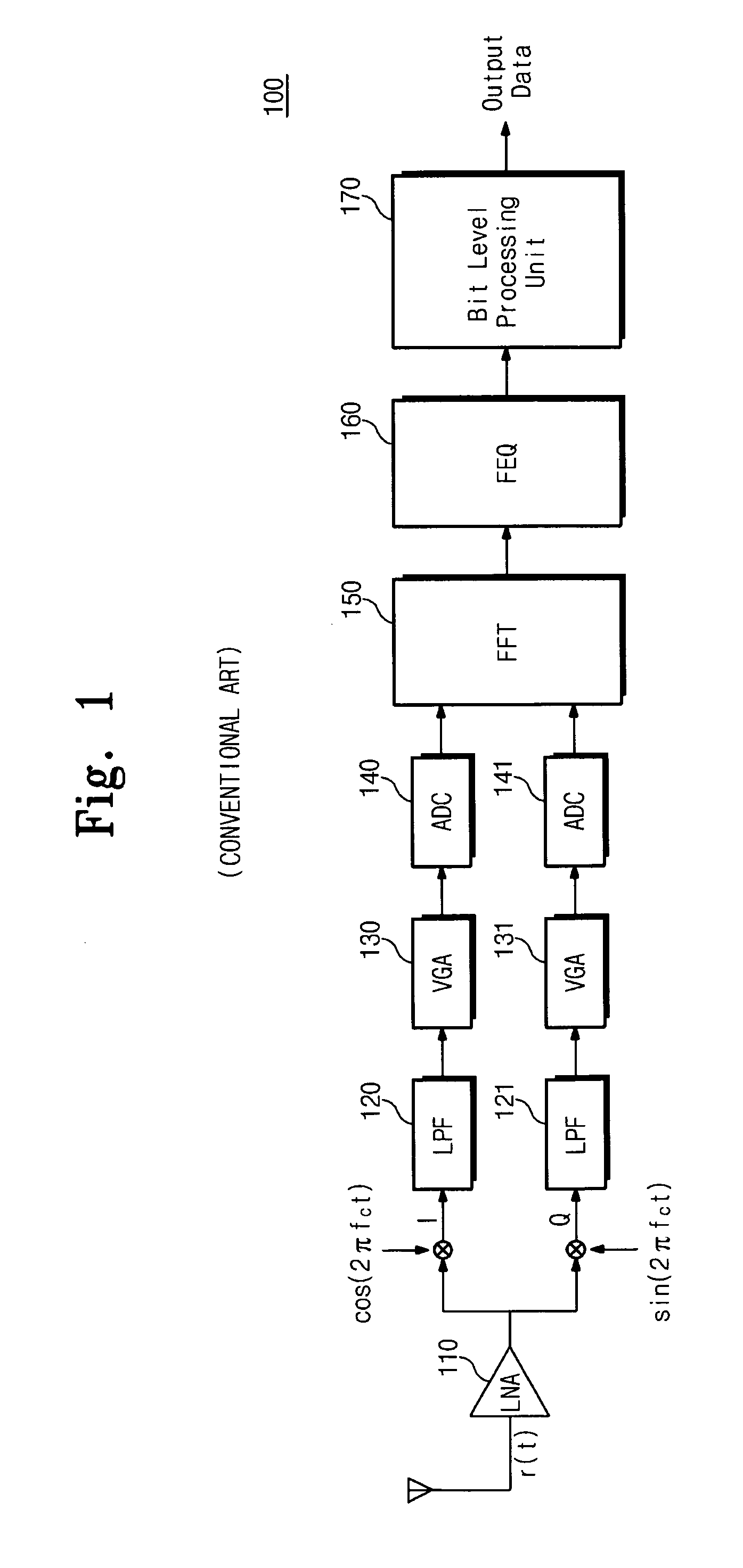
Therefore, an idle time of operation may exist in the bit-level processing unit 170, whereby static power consumption may still remain.
The static and dynamic power consumption may act as a large factor of power dissipation in the UWB system.

Method used


Image

  • UWB Receiver scaling clock frequency by data rate and data reception method thereof
  • UWB Receiver scaling clock frequency by data rate and data reception method thereof
  • UWB Receiver scaling clock frequency by data rate and data reception method thereof

Examples


Embodiment Construction

[0029]Detailed example embodiments are disclosed herein. However, specific structural and functional details disclosed herein are merely representative for purposes of describing example embodiments. Accordingly, example embodiments are capable of various modifications and alternative forms. It should be understood, however, that there is no intent to limit example embodiments to the particular forms disclosed, but on the contrary, example embodiments are to cover all modifications, equivalents, and alternatives falling within the scope of the application.

[0030]It will be understood that, although the terms first, second, etc. may be used herein to describe various elements, these elements should not be limited by these terms. These terms are only used to distinguish one element from another. For example, a first element could be termed a second element, and, similarly, a second element could be termed a first element, without departing from the scope of example embodiments. As used...


PUM


Abstract

A method for demodulating an ultra-wide band (UWB) signal includes detecting a detecting a data rate of the UWB signal, selecting one from plurality of clock signals in response to the detected data rate, decoding the UWB signal in accordance with the selected clock signal, and outputting transmission data determined by a fast clock. The plurality of clock signals includes at least one frequency different from other frequencies. A receiver for an UWB signal includes an OFDM demodulating unit demodulating the UWB signal into an OFDM symbol, and a bit-level processing unit demodulating the OFDM symbol into bit-level data. The bit-level processing unit receives a scaled clock signal having a frequency corresponding to one of a plurality of data rates of the UWB signal. The method and apparatus may reduce static power consumption and improve performance of the receiver.

Description

PRIORITY STATEMENT[0001]This U.S. non-provisional patent application claims the benefit of Korean Patent Application No. 10-2007-20419, filed on Feb. 28, 2007, in the Korean Intellectual Property Office, the disclosure of which is incorporated herein in this entirety by reference.BACKGROUND[0002]1. Field[0003]Example embodiments relate to a radio transmitter-receiver system, for example, to a method and apparatus for managing clock signals in an ultra-wide band (UWB) reception system.[0004]2. Description of the Related Art[0005]A UWB reception system is a type radio technology that enables data transmission in ultrahigh frequency with relatively low power. The UWM system may effectively utilize frequency resources by sharing frequency spectrums of traditional communication systems, thereby providing increased reliability. The characteristics of low power and increased reliability may make UWB technology ideal for radio frequency sensitive environments, such as, collision protecting ...

Claims


Application Information

Patent Timeline
Patent Type & Authority Applications(United States)
IPC IPC(8): H04L7/00H04L25/00H04L25/40
CPCH04B1/69H04L1/0054H04L5/0007H04L2027/0034H04L27/0014H04L27/2657H04L25/0262H04B1/06H04L27/26
Inventor KWAK, JAE-YOUNG
Owner SAMSUNG ELECTRONICS CO LTD
Why Eureka
Try Eureka