
Adjustable axial rotor discharge deflector

Active Publication Date: 2008-08-28
BLUE LEAF I P
View PDF28 Cites 8 Cited by
  • Summary
  • Abstract
  • Description
  • Claims
  • Application Information

AI Technical Summary

Benefits of technology

[0016]What is disclosed is an adjustable axial rotor discharge deflector apparatus, and method of use thereof, for better transitioning crop residue from an axially arranged threshing system of a combine to a crop residue distribution system that overcomes one or more of the problems and disadvantages set forth hereinabove and which achieves the improved performance and reliability as also discussed hereinabove.
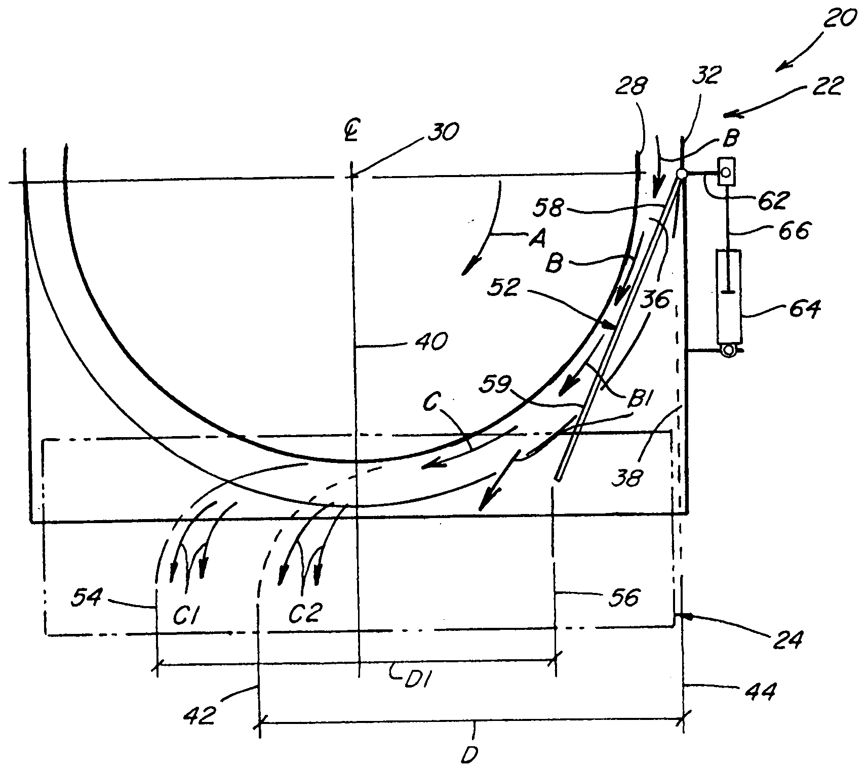
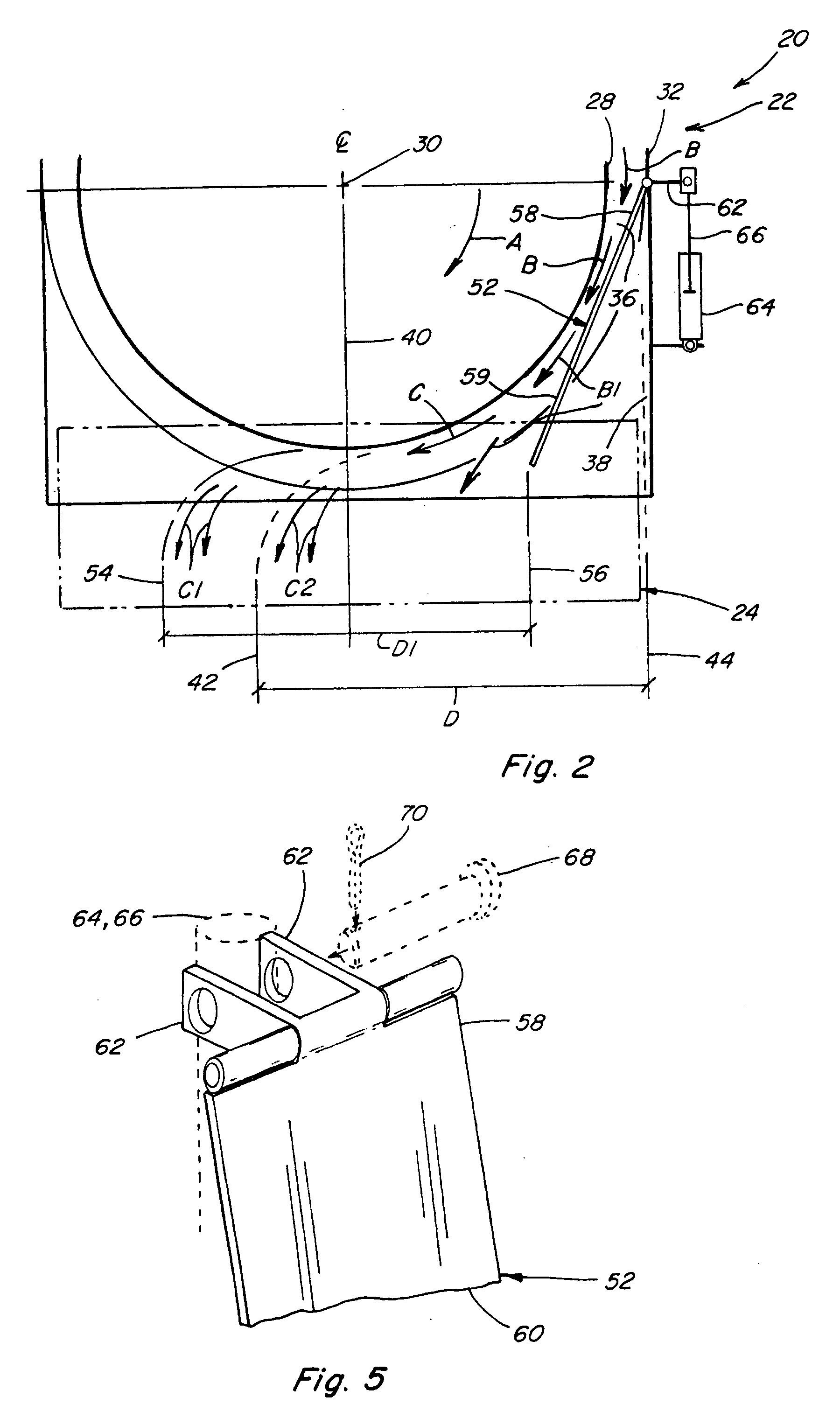
[0018]In accordance with one aspect of the invention, a deflector apparatus is disposed in a position in the discharge opening leading to a crop residue distribution system of the combine such that at least a portion of the downward crop residue flow will strike or impinge a deflector plate thereof and be deflected thereby transversely by a desired amount so as to extend in a desired manner through a more central region of the discharge passage toward the crop residue distribution system. In a preferred embodiment, such deflector apparatus includes a deflector plate having an upper end hingedly or pivotally mounted at or after the downstream end of the threshing rotor at an elevation approximately the same height as the axis of the rotor at its downstream end, and a free, depending portion extending therefrom and being rotatable about the hinge or pivot axis to be positionable within the path of the crop residue being discharged at the downstream end of the rotor. An associated adjusting mechanism is operable for moving the deflector plate in relation to the internal side of the combine for adjusting a desired parameter or parameters of the downwardly deflected flow, which can include, but are not limited to, a transverse location at which the flow will enter the crop residue distribution system. As a result, heavier inflow of crop residue into a side of the discharge opening can be intercepted at a more elevated position and transversely redirected so as to provide better side-to-side or transverse distribution of the crop residue flow through the discharge passage and into the crop residue distribution system. As a consequence, the crop residue distribution system will be better able to feed the crop residue more evenly into a chopper and / or spreader located on the rear end of the combine, resulting in more even and uniform distribution of the crop residue over a swath of a field from which the crop has been harvested.
[0022]In some preferred embodiments, the leading edge of the deflector plate may be tapered in order to secure and facilitate a more uniform flow of crop residue in the discharge passage. The heavier or greater flow being expelled from the rotor residue passage near the concave surface on the downward swept side of the rotor can be more fully intercepted and redirected by a broader portion of the face of the deflector plate nearer the upper portion of the deflector plate while the relatively lighter flow being expelled closer to the axis of the rotor near the rotor surface will be subject to less redirection due to the tapering of the leading edge and the narrower portion of the face of the deflector plate at the face end of the deflector plate. Such tapering allows for improved uniformity of flow through the discharge passage.
[0023]In one of such preferred embodiments, the face of the lower portion of such deflector plate may also include an outwardly projecting directional vane disposed thereon for intercepting a portion of the flow of crop residue across the face of the deflector plate and redirecting that flow in a desired manner into the crop residue distribution system. Such vane, especially in conjunction with the interception of a portion of the flow of crop residue at a greater elevation above the crop residue distribution system as it is being discharged from a side of the rotor residue passage into the discharge passage and to a crop residue distribution system of the combine, affords better control of the crop residue flow to achieve a more uniform distribution of the crop residue to the crop residue distribution system.

Problems solved by technology

This is desirable for reasons including that uneven crop residue distribution on a field can lead to temperature and moisture gradients detrimental to even growth of future crops on the field.
It can also make it difficult for crops to utilize nutrients, and can impact the effectiveness of agricultural chemicals.
Large discontinuities of crop residue can lead to plugging and other functional problems with tillage and / or planting equipment.
In particular, the side to side distribution of the flow into the rotating beater can vary, that is, flow to one side of the beater can be heavier than to the other side, such that the beater will propel more crop residue into one side of a chopper and / or spreader, resulting, in turn, in uneven crop residue distribution over a swath of a field.
In the absence of such controlled retraction, a rotor reversal can result in the forced deposit of crop residue between the backside of the extended deflector plate and the bulkhead to which it is mounted and the attendant risks of damage to both the deflector plate itself and to the adjustment means therefor as additional crop residue continues to be directed to such location.
Even if the rotor reversal is only for a short duration, when the rotor operation is returned to its original condition, the buildup of crop residue between the backside of the deflector plate and the bulkhead to which it is mounted may be such that it does not properly clear, which can result in the deflector plate remaining in a jammed condition or in subsequent less effective operation and positioning of the deflector plate.

Method used


Image

  • Adjustable axial rotor discharge deflector
  • Adjustable axial rotor discharge deflector
  • Adjustable axial rotor discharge deflector

Examples


Embodiment Construction

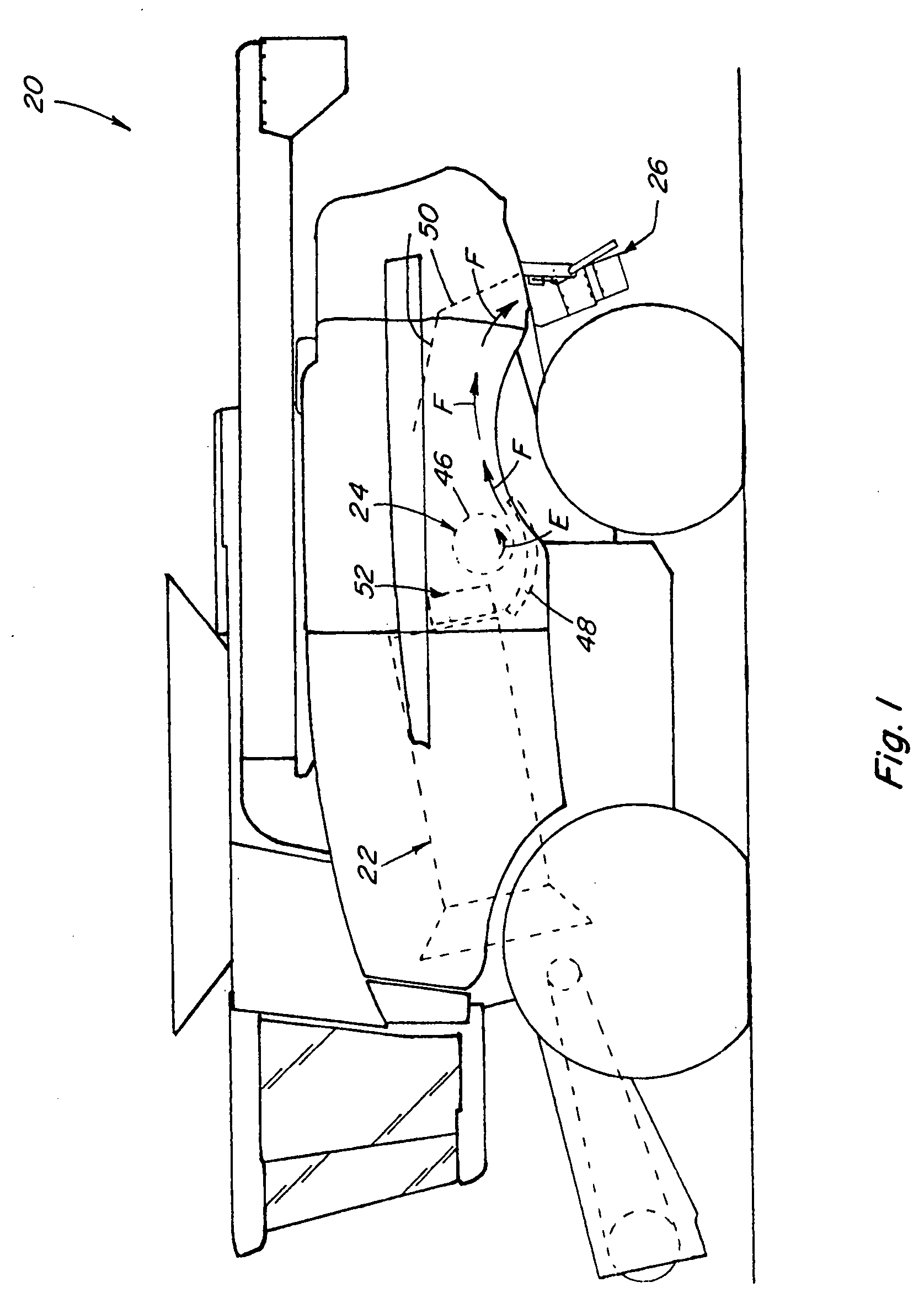
[0042]Referring now to the drawings, wherein preferred embodiments of the present invention are shown and wherein like numerals refer to like items, FIG. 1 depicts a representative agricultural combine 20 that includes an axially arranged threshing system 22, a crop residue distribution system 24, and a crop residue chopper / spreader 26, all of well known construction and operation.

[0043]As can be generally and essentially observed from a review and study of FIGS. 1-4, threshing system 22 is axially arranged in that it includes a cylindrical rotor 28 conventionally supported and rotatable in a predetermined direction, with arrow A in FIG. 2 denoting a typical clockwise, or forward, rotation, about a rotational axis 30 therethrough and within a concave 32, for conveying a flow of crop material in a helical flow path through a space 34 extending circumferentially around an outer cylindrical surface 35 of rotor 28 and an inner circumferential surface of concave 32. As the crop material ...


PUM


Abstract

An adjustable deflector apparatus having a deflector plate for transitioning crop residue from the rotor of an axially arranged threshing system of a combine to a crop residue distribution system is disposed with the deflector plate pivotally mounted at approximately the height of the axis of the rotor at its downstream end to be movable into and out of the flow of the crop residue such that at least a portion of such flow will strike or impinge the deflector plate and be deflected thereby downwardly and transversely toward the crop residue distribution system. An adjusting mechanism is operable for moving the deflector plate in relation to an internal side of the combine for adjusting a desired parameter or parameters of the deflected flow and for moving the deflector plate to a retracted position when reverse operation of the rotor is desired.

Description

TECHNICAL FIELD[0001]This invention relates generally to an apparatus for transitioning or redirecting a flow of crop residue from an axially arranged threshing or separating system of an agricultural combine so as to flow more evenly into a crop residue distribution system for distributing the residue onto a field, and more particularly, to an apparatus including a crop residue flow deflector plate which is adjustably positionable within a range of positions so as to be impinged to a desired extent by a flow of crop residue from an axially extending rotor and concave assembly, for transitioning or deflecting the flow to the residue distribution system for achieving desired or required operational characteristics such as a particular transverse location, pattern and / or evenness of crop residue distribution on a harvested field, and to a method of operation thereof in the event of reverse rotor operation.BACKGROUND ART[0002]Axially arranged rotary threshing or separating systems have...

Claims


Application Information

Patent Timeline
IPC IPC(8): A01F12/30
CPCA01F7/06A01F7/067
Inventor ISAAC, NATHAN E.
Owner BLUE LEAF I P
Learn More