Laser energy device for soft tissue removal

a laser energy device and soft tissue technology, applied in the field of laser energy devices for soft tissue removal, can solve the problems of fiber charring, increased potential for occlusion and efficiency, and potential issue of occlusion of cannula, so as to reduce efficiency, reduce cross sectional area, and increase potential for occlusion

Inactive Publication Date: 2008-08-28
CURVE MEDICAL LLC
View PDF10 Cites 107 Cited by
  • Summary
  • Abstract
  • Description
  • Claims
  • Application Information

AI Technical Summary

Benefits of technology

[0006]While the laser energy devices described above have provided many beneficial characteristics and attributes, the chance of occlusion of the cannula has been identified as a potential issue due to the laser fiber guide tube being located totally or partially inside the lumen of the cannula. The inclusion of the laser fiber guide tube inside the cannula results in a decreased cross sectional area within the cannula and thereby a higher potential for occlusion and decreased efficiency. The location of the tip of the laser fiber also increases the likelihood of the aspirated soft tissue coming into direct contact with the laser fiber tip resulting in fiber charring. In general, the devices of the present invention can include many of the same or similar components as the laser energy devices described above. Embodiments of such devices, components and their methods of manufacture and use are disclosed and/or suggested in U.S. Pat. Nos. 4,985,027 and 5,102,410, the contents of which are incorporated by reference herein. However, in various embodiments of the present invention the laser guide tube is located inside the handle at the proximal end of the cannula, but it is located outside of

Problems solved by technology

While the laser energy devices described above have provided many beneficial characteristics and attributes, the chance of occlusion of the cannula has been identified as a potential issue due to the laser fiber guide tube being located totally or partially inside the lumen of the cannula.
The inclusion of the laser fiber guide tube inside the cannula results in a decreased cross sectional area within the cannula and thereb

Method used


Image

  • Laser energy device for soft tissue removal
  • Laser energy device for soft tissue removal
  • Laser energy device for soft tissue removal

Examples


Embodiment Construction

[0026]The embodiments of the present invention described below are not intended to be exhaustive or to limit the invention to the precise forms disclosed in the following detailed description. Rather, the embodiments are chosen and described so that others skilled in the art can appreciate and understand the components, principles and practices of the present invention.

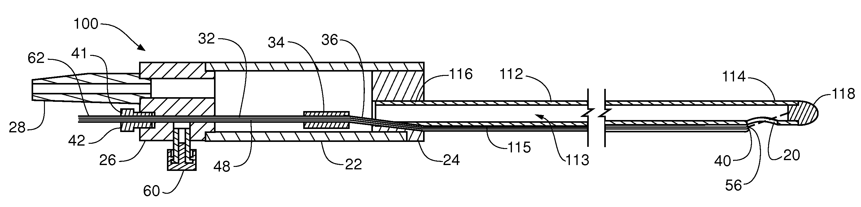
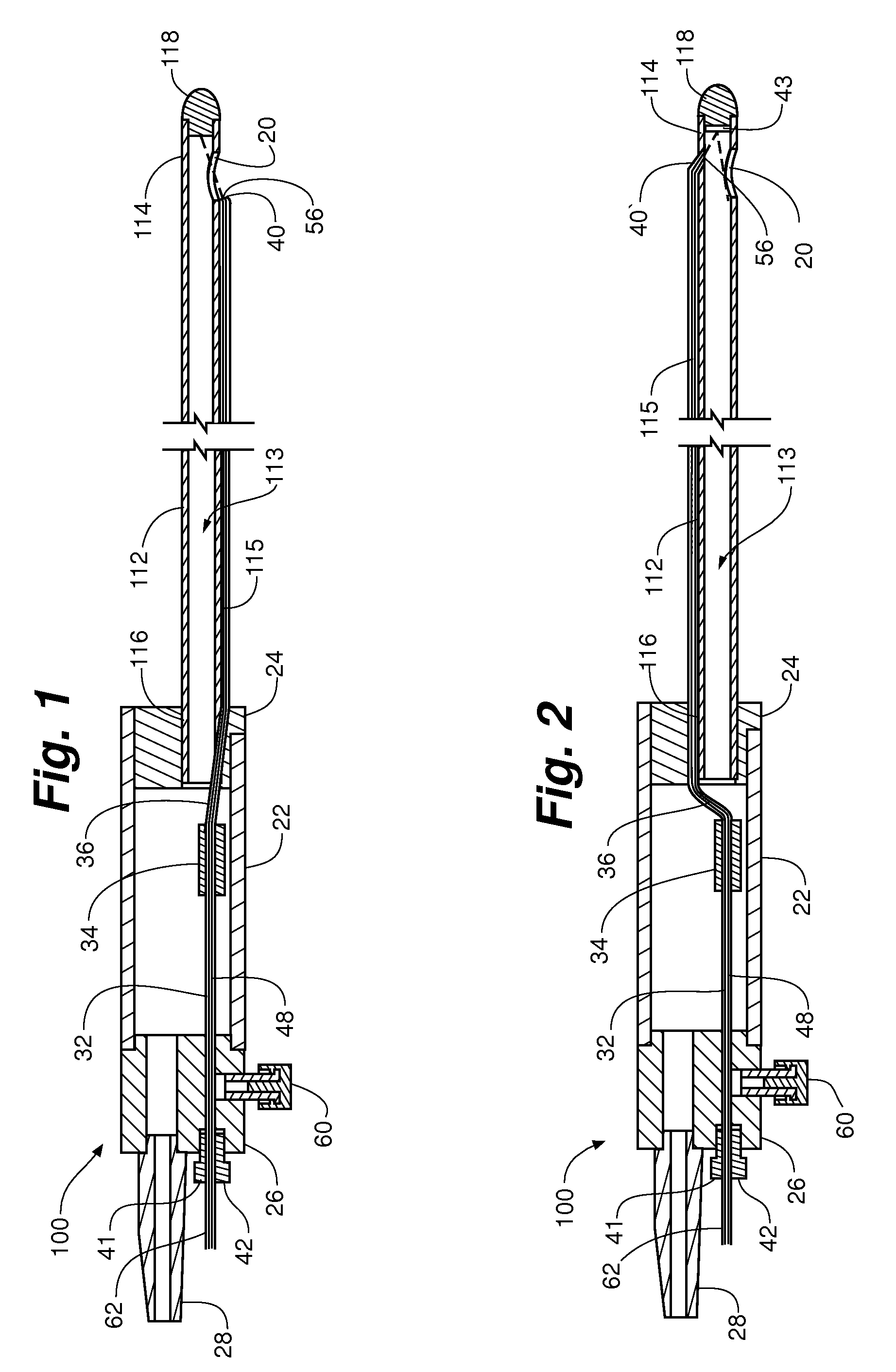
[0027]FIGS. 1, 2 and 10 depict embodiments of a laser soft tissue aspiration device 100 wherein the device comprises an aspiration cannula 112, a laser guide tube 36, an aspiration inlet port 20, and a laser energy transmission guide 115. The aspiration cannula 112 includes a lumen 113 providing for fluid and / or soft tissue flow within the cannula 112. The lumen 113 is in communication with one or more aspiration inlet ports 20 at a distal end 114 of the aspiration cannula 112. An aspirated soft tissue outlet port 28 at a proximal end 116 of the device 100 and in fluid flow connection to the lumen 13can couple an aspi...


PUM


Abstract

This invention relates to a device and method for improving the surgical procedure of soft tissue removal by aspiration and more particularly to a device and method utilizing laser energy directed substantially across the inlet port to more readily and safely facilitate the separating of soft tissue from a patient in vivo. This invention has immediate and direct application to the surgical procedure of liposuction or body contouring as well as application in the surgical procedures of other soft tissue removal such as brain tissue, eye tissue, and other soft tissue inaccessible to other soft tissue aspiration techniques.

Description

FIELD OF THE INVENTION[0001]This invention relates to a device and method for improving the surgical procedure of soft tissue removal by aspiration and more particularly to a device and method utilizing laser energy directed at the edge of the inlet port to more readily and safely facilitate the separating of soft tissue from a patient in vivo. This invention has immediate and direct application to the surgical procedure of liposuction or body contouring as well as application in the surgical procedures of other soft tissue removal such as brain tissue, eye tissue, and other soft tissue.BACKGROUND OF THE INVENTION[0002]Within the past decade, the surgical use of lasers to cut, cauterize and ablate tissue has been developing rapidly. Advantages to the surgical use of laser energy lie in increased precision and maneuverability over conventional techniques. Additional benefits include prompt healing with less post-operative pain, bruising, and swelling. Lasers have become increasingly ...

Claims


Application Information

Patent Timeline
IPC IPC(8): A61B18/20A61M1/00
CPCA61B18/22A61B2017/00084A61M2202/08A61B2019/464A61M1/008A61B2017/00123A61B2090/064A61M1/89A61B2218/007
Inventor ZELICKSON, BRIAN D.DRESSEL, THOMAS
Owner CURVE MEDICAL LLC
Why Eureka
Try Eureka