Ostial stent preforming apparatus, kits and methods

a technology of ostial stent and pre-forming equipment, which is applied in the field of ostial stent pre-forming equipment, kits and methods, can solve the problems of patient complications, difficult placement of stents within vasculature, and placement of stents to repair diseased vessels that are branch vessels, etc., and achieve the effect of constant diameter and constant diameter

Active Publication Date: 2008-08-28
MAYO FOUND FOR MEDICAL EDUCATION & RES
View PDF4 Cites 5 Cited by
  • Summary
  • Abstract
  • Description
  • Claims
  • Application Information

AI Technical Summary

Benefits of technology

[0010]In one aspect, the present invention provides an apparatus for flaring a stent, the apparatus including a sterile body having a first end and a second end; a sterile bore formed through the body, the bore having a first opening at the first end and a second opening at the second end, wherein the bore has a first portion proximate the first end and a second portion proximate the second end, wherein the first portion and the second portion meet within the bore, and wherein the first portion has a flared diameter that decreases when moving from the first end towards the second end and the second portion has a substantially constant diameter; and a sterile clamp mechanism located proximate the second opening.
[0011]In other aspects, the apparatus may include one or more additional sterile bores formed through the body; wherein each of the additional bores has a first opening at the first end and a second opening at the second end, wherein the additional bore has a first portion proximate the first end and a second portion proximat...

Problems solved by technology

Angioplasty procedures are widely accepted for treatment of occluded arteries, the problem of restenosis following the angioplasty treatment is, however, a complication a patient must face.
Placement of the stent within the vasculature can be especially challenging when the stenotic region is near the intersection of two vessels or is at the origin of a major vessel off the aorta.
For example, the placement of a stent to repair a diseased vessel that is a branch vessel, such as the renal artery, near its ostium with a great vessel, such as the aorta, is particularly challenging because the stent must be securely and precisely positioned in an area that supports a heavy volume of blood flow without occluding the blood flow in either the branch vessel or the great vessel.
Additionally, the angle created by the intersection of a main/great vessel and a branch vessel can lead to difficulties in precisely positioning the stent in the damaged branch vessel.
Physicians often have difficulty aligning the stent to optimally repair the steno...

Method used


Image

  • Ostial stent preforming apparatus, kits and methods
  • Ostial stent preforming apparatus, kits and methods
  • Ostial stent preforming apparatus, kits and methods

Examples


Embodiment Construction

[0024]In the following detailed description of illustrative embodiments of the invention, reference is made to the accompanying figures of the drawing which form a part hereof, and in which are shown, by way of illustration, specific embodiments in which the invention may be practiced. It is to be understood that other embodiments may be utilized and structural changes may be made without departing from the scope of the present invention.

[0025]A variety of documents describe the advancement and placement of stents within vessels, including the advancement and placement of ostial stents. See, e.g., U.S. Patent Application Publication Nos. US 2002 / 0077691 (Nachtigall); US 2002 / 0091434 (Chambers); US 2004 / 0111143 (Fischell et al.); etc.—as well as U.S. Pat. No. 5,607,444 (Lam); U.S. Pat. No. 5,749,890 (Shaknovich); etc.

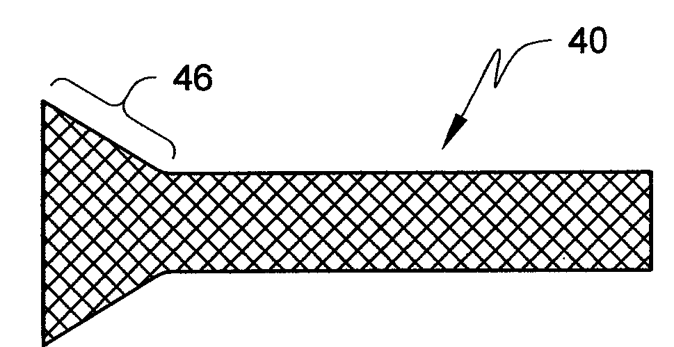
[0026]The stents that can be used in connection with the present invention may include, e.g., any conventional stent that can be deformed to include a flared end suitabl...


PUM

PropertyMeasurementUnit
Lengthaaaaaaaaaa
Diameteraaaaaaaaaa
Shapeaaaaaaaaaa

Abstract

Apparatus, kits and methods for flaring an end of a stent that can then be placed within the ostium of a vessel are disclosed. Areas in which ostial stents with flared ends could be used may include, e.g., the left main artery, renal arteries, sub-clavian artery, right coronary artery, circumflex artery, et al.

Description

[0001]The present invention relates generally to apparatus, kits and methods for modifying stents for ostial placement.[0002]Angioplasty procedures are widely accepted for treatment of occluded arteries, the problem of restenosis following the angioplasty treatment is, however, a complication a patient must face. Restenosis is the reclosure or renarrowing of an artery following trauma caused by angioplasty to open an occluded portion of the artery. Renarrowing is also frequently caused by the elastic rebound of the arterial wall and / or by dissections in the vessel wall caused by the angioplasty procedure.[0003]To combat restenosis and maintain the patency of the vessel lumen, physicians implant tubular supports known as stents into surgically repaired vessels.[0004]Stents are used to address restenosis in many patients. The stent is typically inserted by catheter into a vascular lumen at an easily accessible location, such as the brachial or femoral arteries, and then is advanced th...

Claims


Application Information

Patent Timeline
IPC IPC(8): A61F2/82
CPCA61F2/82A61F2002/9522A61F2002/821A61F2/958A61F2/9522
Inventor SANDHU, GURPREET S.
Owner MAYO FOUND FOR MEDICAL EDUCATION & RES
Why Eureka
Try Eureka