Driving mechanism and cutting apparatus having the driving mechanism
- Summary
- Abstract
- Description
- Claims
- Application Information
AI Technical Summary
Benefits of technology
Problems solved by technology
Method used
Image
Examples
Embodiment Construction
[0021]A cutting apparatus 1 shown in FIG. 3 is an apparatus for cutting various works, which has at least a driving mechanism 2 having the function of moving a chuck, table 23 for holding the work. The driving mechanism 2 includes a pair of guide rails 20 disposed in an X-axis direction, a sliding body 21 capable of being slid in engagement with the guide rails 20, a driving unit 22 for moving the sliding body 21 along the guide rails 20, and the chuck table 23 which is an active element fixed to the sliding body 21.
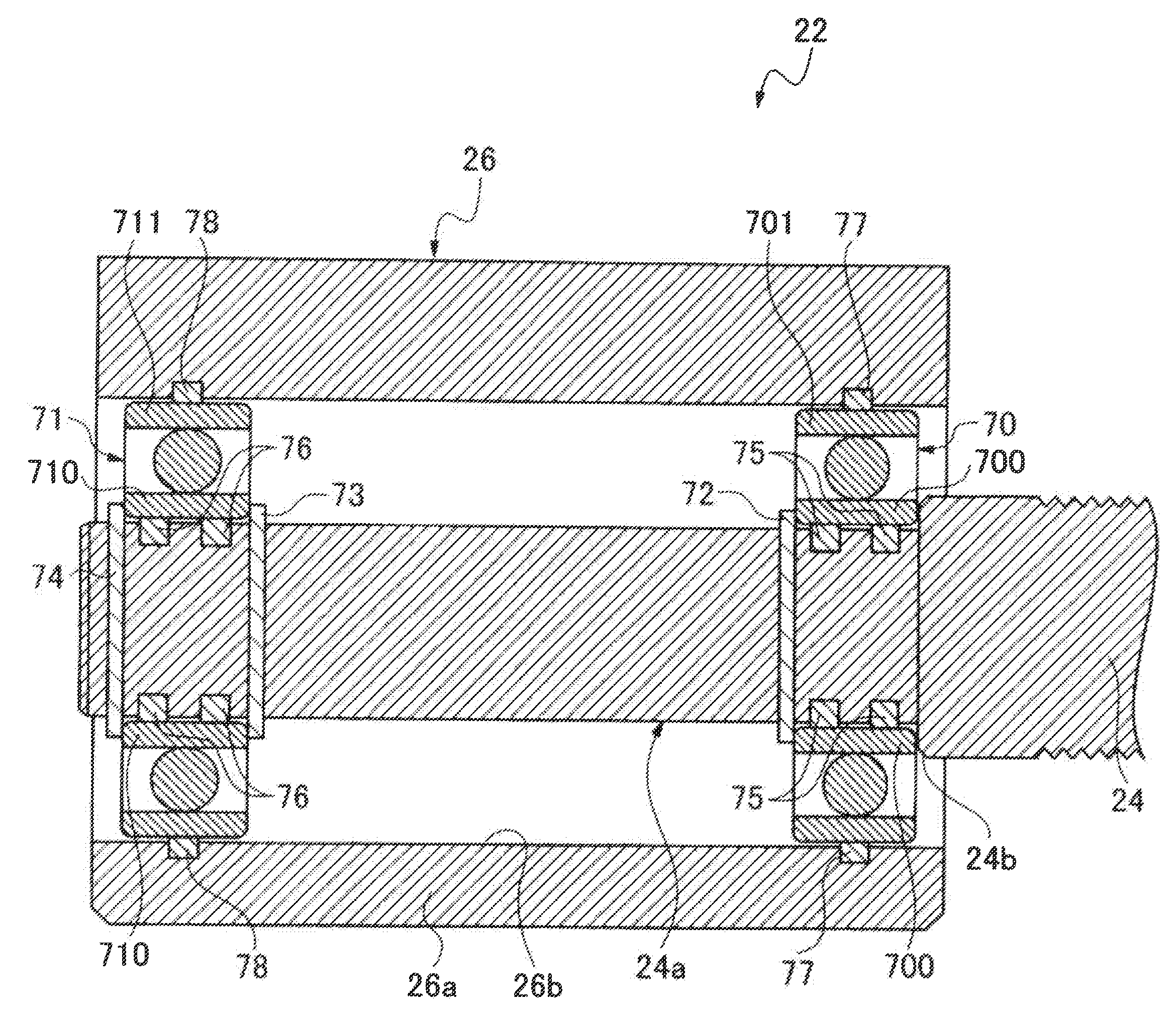
[0022]The driving unit 22 includes a feed, screw shaft 24 disposed in parallel, to the guide rails 20, a drive source 25 connected to one end of the feed screw shaft 24 and operative to rotate the feed screw shaft 24, a terminal support part 26 for rotatably supporting a free end part 24a of the feed screw shaft 24, and a feed nut (not shown) in screw engagement with the feed screw shaft 24 and connected to the chuck table 23 (which is the active element) through the sli...
PUM
| Property | Measurement | Unit |
|---|---|---|
| Elasticity | aaaaa | aaaaa |
Abstract
Description
Claims
Application Information
 - R&D
- Intellectual Property
- Life Sciences
- Materials
- Tech Scout
- Unparalleled Data Quality
- Higher Quality Content
- 60% Fewer Hallucinations
Browse by: Latest US Patents, China's latest patents, Technical Efficacy Thesaurus, Application Domain, Technology Topic, Popular Technical Reports.
© 2025 PatSnap. All rights reserved.Legal|Privacy policy|Modern Slavery Act Transparency Statement|Sitemap|About US| Contact US: help@patsnap.com


