Leg Joint Assist Device of Legged Mobile Robot

a mobile robot and assist device technology, applied in the direction of couplings, manufacturing tools, transportation and packaging, etc., can solve the problems of increasing the energy consumed by the joint actuator in some cases, the difficulty of restrainting the generated eventually energy consumption, and the inability to achieve a further reduction in energy consumption. achieve the effect of reducing the burden on the joint actuator of the knee joint, preventing the increasing driving force of the joint actuator, and preventing the excessive assisting

Inactive Publication Date: 2008-09-04
HONDA MOTOR CO LTD
View PDF4 Cites 43 Cited by
  • Summary
  • Abstract
  • Description
  • Claims
  • Application Information

AI Technical Summary

Benefits of technology

[0024]With this arrangement, if the flexing degree of each leg exceeds the second predetermined amount, the assisting driving force will be smaller than the assisting driving force predetermined value, which is the value of the assisting driving force when the flexing degree is set to agree with the second predetermined amount, or will be approximately equal to the assisting driving force predetermined value. This makes it possible to prevent the assisting driving force from becoming excessive in a state wherein each leg is apart from a floor (in a state wherein the flexing degree of each leg exceeds the second predetermined amount). As a result, it is possible to prevent the driving force of a joint actuator from increasing in a period during wh...

Problems solved by technology

For this reason, even if a required driving force to be generated at the knee joint of each leg is small, there are cases where a driving force for canceling the elastic force of the spring must be produced in the joint actuator of the knee joint, resulting in an increase in the energy consumed by the joint actuator in some cases.
Especially in the one disclosed in Patent Document 1, the elastic force of the spring increases as the flexing angle of the leg at the knee joint increases, so that a driving force generated at the joint actuator in a free leg period of a leg, during which the required driving force to be generated at the knee joint should be small, will be inevitably large, thus making it difficult to restrain a generated driving force of the joint actuator and eventually energy consumption.
However, the flexing angle of the knee joint at which the elastic force of the gas spring is zero is limited to...

Method used


Image

  • Leg Joint Assist Device of Legged Mobile Robot
  • Leg Joint Assist Device of Legged Mobile Robot
  • Leg Joint Assist Device of Legged Mobile Robot

Examples


Embodiment Construction

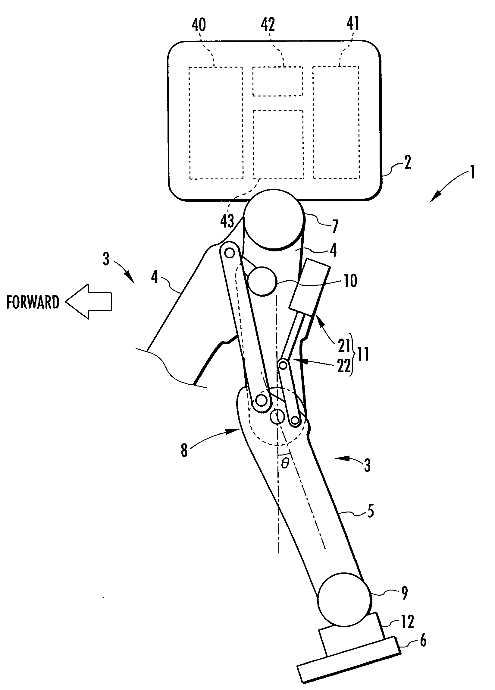
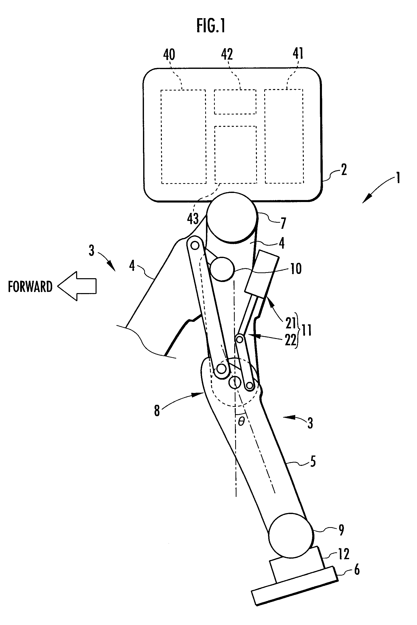
[0026]A first embodiment of the present invention will be explained with reference to FIG. 1 to FIG. 7. FIG. 1 is a diagram schematically showing the construction of a bipedal mobile robot as a legged mobile robot in the present embodiment. As shown in the figure, a robot 1 is equipped with two legs 3 and 3 extendedly provided downward from a body 2, which is a base thereof. These legs 3 and 3 share the same structure, including an assist device, which will be discussed later, so that only a part of one leg 3 (the leg 3 on the right side as observed toward the front of the robot 1 in the figure) is shown in the figure.

[0027]As with the legs of a human being, each leg 3 is constructed by a thigh 4, a crus 5, and a foot 6 consecutively connected in order through the intermediary of a hip joint 7, a knee joint 8, and an ankle joint 9 from the body 2. More specifically, the thigh 4 of each leg 3 is extended from the body 2 through the intermediary of the hip joint 7, the crus 5 is conne...


PUM


Abstract

An assist device 11 is equipped with a spring means 21 (gas spring), and a piston 24 in a cylinder 23 moves upward or downward according to a relative displacement motion (flexing or stretching motion) of a thigh 4 and a crus 5 at a knee joint 8 of a leg 3 of a robot. Air chambers 25 and 26 above and below the piston 24 are filled with gases. If a flexing degree at the knee joint 8 is a predetermined value or less, then the air chambers 25 and 26 are brought into communication through a groove 28 in the cylinder 23, and the spring means 21 does not generate an elastic force, but if the flexing degree exceeds the predetermined value, then the air chambers 25 and 26 are hermetically sealed from each other and the spring means 21 produces an elastic force, the elastic force acting on the knee joint 8 as assisting driving force. A burden on a joint actuator of a leg can be reduced, while reducing energy consumption of the robot by using a small and simple construction. Moreover, a change in the characteristics of an assisting driving force of the spring means 21 in response to a flexing degree of the knee joint 8 can be restrained.

Description

TECHNICAL FIELD [0001]The present invention relates to a leg joint assist device for generating an assisting driving force in a joint of a leg of a legged mobile robot, such as a bipedal mobile robot, the assisting driving force assisting a joint actuator for driving the joint.BACKGROUND ART[0002]Hitherto, as this type of assist device, there have been known one shown in FIG. 9 of Japanese Patent Application Publication No. 2001-198864 (hereinafter referred to as Patent Document 1) and one disclosed in Japanese Patent Application Publication No. 2003-145477 (hereinafter referred to as Patent Document 2) and one disclosed in Japanese Patent Application Publication No. 2003-103480 (hereinafter referred to as Patent Document 3) previously proposed by the present applicant.[0003]The one disclosed in Patent Document 1 includes a spring provided between two link members (a thigh and a crus) connected by a knee joint of each leg of a bipedal mobile robot, a flexing or stretching motion of ...

Claims


Application Information

Patent Timeline
IPC IPC(8): B62D51/04F16C11/00
CPCB25J19/0012Y10T403/32606B62D57/032B25J17/00B25J5/00
Inventor TAKENAKA, TORUGOMI, HIROSHIHAMAYA, KAZUSHIAKIMOTO, KAZUSHISHIROKURA, SHINYAASATANI, MINAMITANAKA, KATSUSHI
Owner HONDA MOTOR CO LTD
Why Eureka
Try Eureka