De-Gassing Lubrication Reclamation System

Active Publication Date: 2008-09-04
CARRIER CORP
View PDF9 Cites 25 Cited by
  • Summary
  • Abstract
  • Description
  • Claims
  • Application Information

AI Technical Summary

Benefits of technology

[0005]The present invention is directed to a vapor compression system for use in a chiller. The vapor compression system includes a lubrication reclamation system, or still, which incorporates an ejector to reduce a pressure in the still. The ejector includes an input portion, an output portion and a vent portion. The input portion, the output portion and the vent portion are in fluid communication with one another. The still pri

Problems solved by technology

The lubricant-refrigerant mixture collects in the evaporator, where it may degrade the heat transfer capability of the system if not reclaimed.
Therefore, upon reclamation, the lubricant-refrigerant mixture may not be suitable for use as a lubricant.
However, at some pressure-temperature conditions encountered by chillers, it can be

Method used


Image

  • De-Gassing Lubrication Reclamation System
  • De-Gassing Lubrication Reclamation System
  • De-Gassing Lubrication Reclamation System

Examples


Embodiment Construction

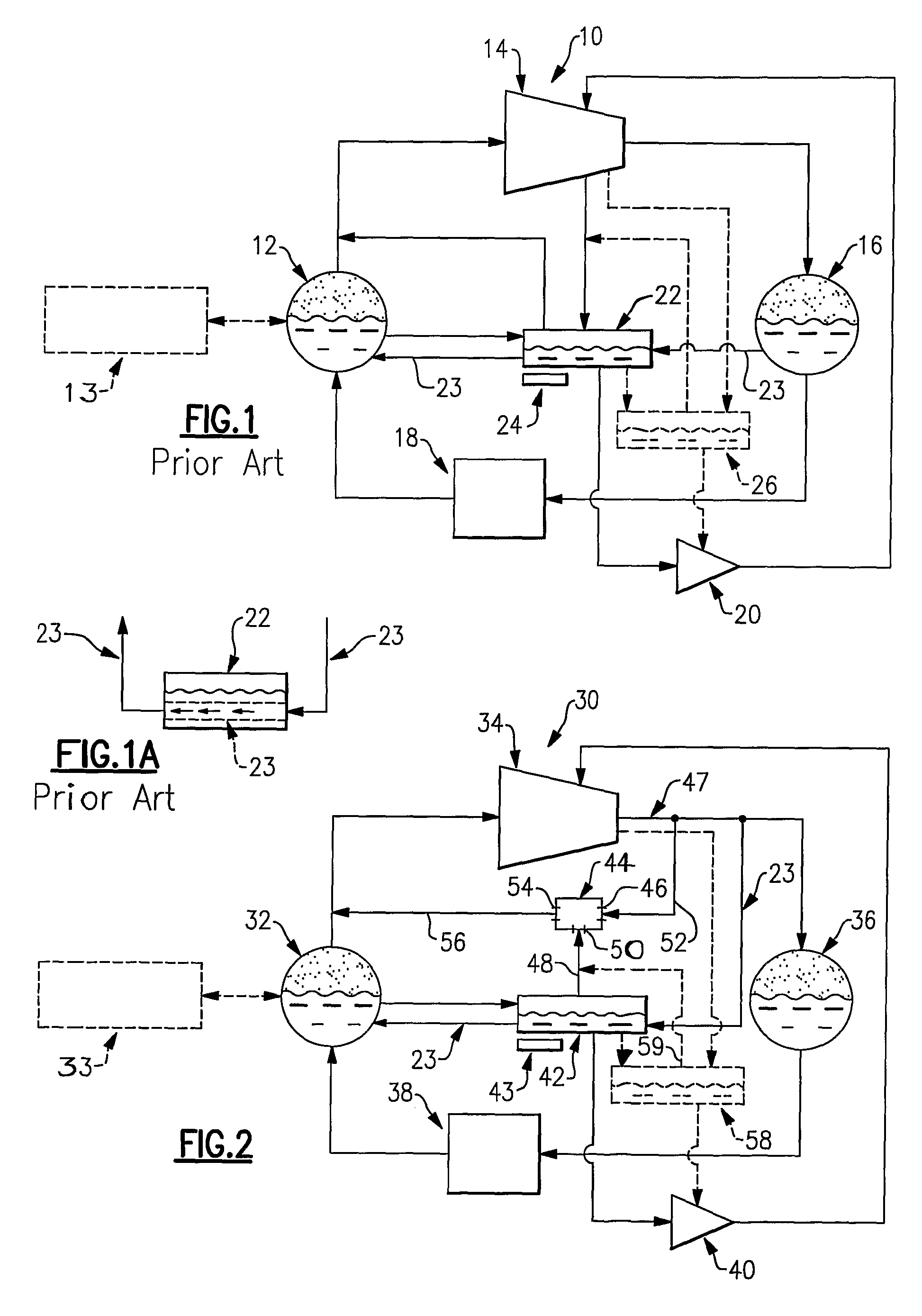
[0014]FIG. 1 is a schematic illustration of a known vapor compression system 10 including a refrigeration loop and a lubrication loop. The refrigeration loop includes an evaporator 12, a compressor 14, a condenser 16 and an expansion device 18. The lubrication loop includes the compressor 14, an oil pump 20 and a still 22.

[0015]In the refrigeration loop, the evaporator 12 delivers a gaseous refrigerant to the compressor 14 where the gaseous refrigerant is compressed. The compressed, gaseous refrigerant is delivered to the condenser 16 where the compressed, gaseous refrigerant is cooled to a liquid phase and transferred through the expansion valve 18 back to the evaporator 12. Further, in a chiller system, heat is exchanged between the evaporator 12 and a chiller 13 shown in phantom.

[0016]In the lubrication loop, the oil pump 20 supplies lubricant to the compressor 14 for lubrication. Because the compressor 14 is part of both the refrigeration loop and the lubrication loop, some of t...


PUM


Abstract

A vapor compression system (10), also known as a chiller, includes a refrigeration loop and a lubrication loop. The lubrication loop includes a lubrication reclamation system that further includes a still (42) and an ejector (44) to reduce a pressure in the still (42). The ejector (44) includes an input portion (46), an output portion 54 and a vent portion (50). The input portion (46), the output portion (54) and the vent portion (50) are in fluid communication with one another. The vent portion (50) of the ejector (44) is positioned in a vent line (48) associated with the still (42). The still (42) primarily contains a mixture of liquid refrigerant and lubricant. The input portion (46) of the ejector receives liquid or gas at a high pressure and expels the liquid or gas through the output portion (54) at an intermediate pressure. As the input fluid at a high pressure flows through the ejector (44), a low pressure is created at the vent portion (50). The reduction in pressure in the vent portion (50) causes a suction pressure within the vent portion (50) associated with the still (44), resulting in a portion of the liquid refrigerant vaporizing, leaving a higher viscosity lubricant.

Description

TECHNICAL FIELD[0001]The present invention relates to vapor compression systems, and more particularly to a vapor compression system used in a “chiller” system that has a flooded evaporator and a generator vessel or still to separate lubricant from liquid refrigerant.BACKGROUND OF THE INVENTION[0002]Chillers, which are used to cool vast interior spaces such as airport terminals, shopping malls and officer towers, include vapor compression systems that generally comprise a refrigeration loop and a lubrication loop. The refrigeration loop includes a condenser, an expansion device, an evaporator or cooler, and a compressor. The lubrication loop also includes the compressor and is designed to provide lubrication to the compressor. Because the refrigeration loop and the lubrication loop intersect in the compressor, liquid refrigerant from the refrigeration loop and lubricant from the lubrication loop are allowed to intermingle resulting in a mixture of liquid refrigerant and lubricant. T...

Claims


Application Information

Patent Timeline
IPC IPC(8): C10M175/00F25B1/00
CPCF25B31/004F25B2341/0012F25B43/02
Inventor SHOULDERS, STEPHEN L.
Owner CARRIER CORP
Why Eureka
Try Eureka