
Plasma Panel Based Radiation Detector

a radiation detector and plasma panel technology, applied in the field of radiation detection, can solve the problems of limiting the use of radiation detectors to gains, and limiting the use of radiation detectors in large parts

Inactive Publication Date: 2008-09-04
INTEGRATED SENSORS
View PDF16 Cites 33 Cited by
  • Summary
  • Abstract
  • Description
  • Claims
  • Application Information

AI Technical Summary

Problems solved by technology

These devices, which have been under development primarily for use in high-energy and nuclear physics, have many desirable properties as proportional gas detectors, but are limited to gains on the order of about 106.
Their use however, has been held back in large part due to avalanche-induced secondary effects associated with ion, electron, photon and metastable species feedback, as well as photocathode degradation caused by ion impact.

Method used


Image

  • Plasma Panel Based Radiation Detector
  • Plasma Panel Based Radiation Detector
  • Plasma Panel Based Radiation Detector

Examples


Embodiment Construction

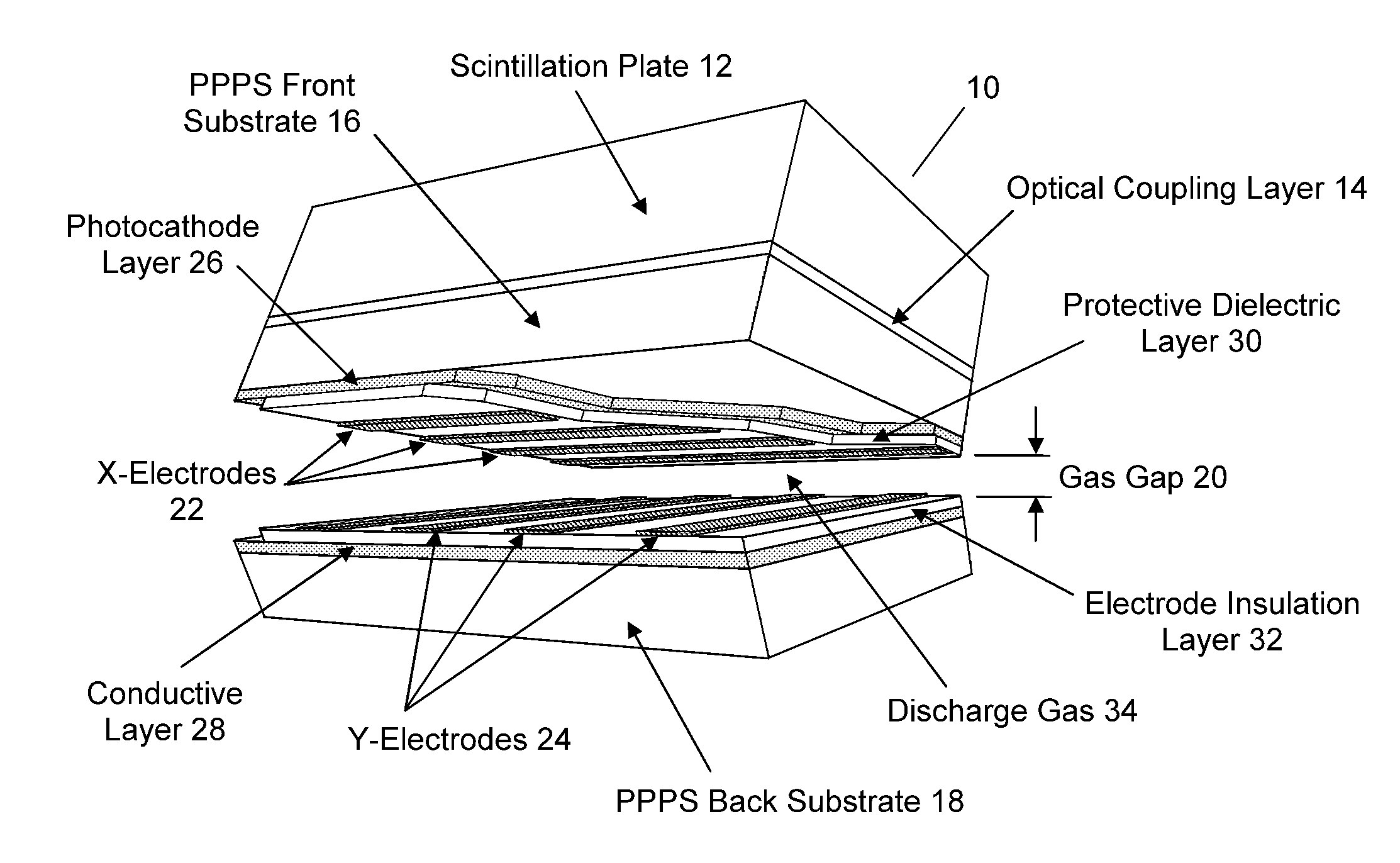
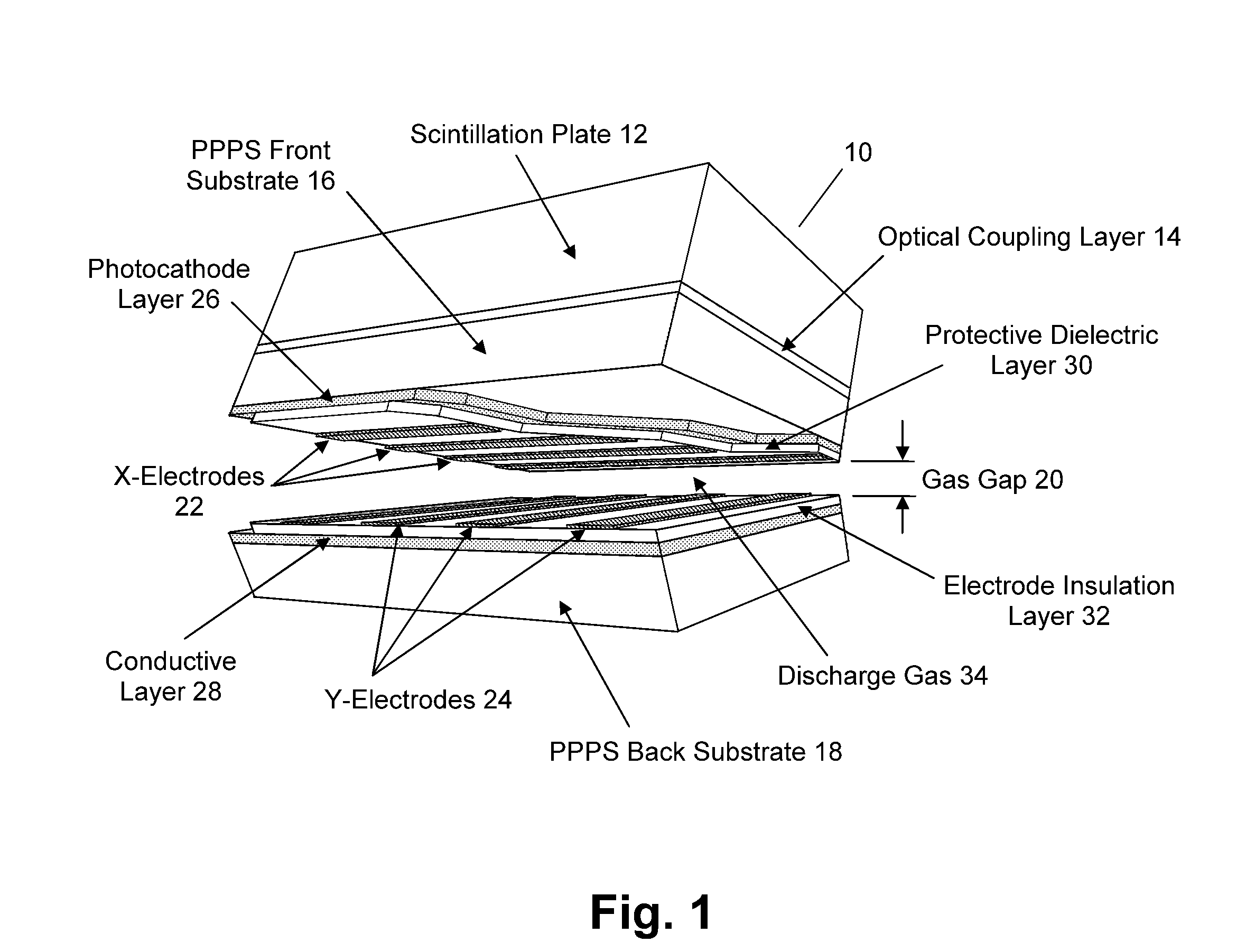
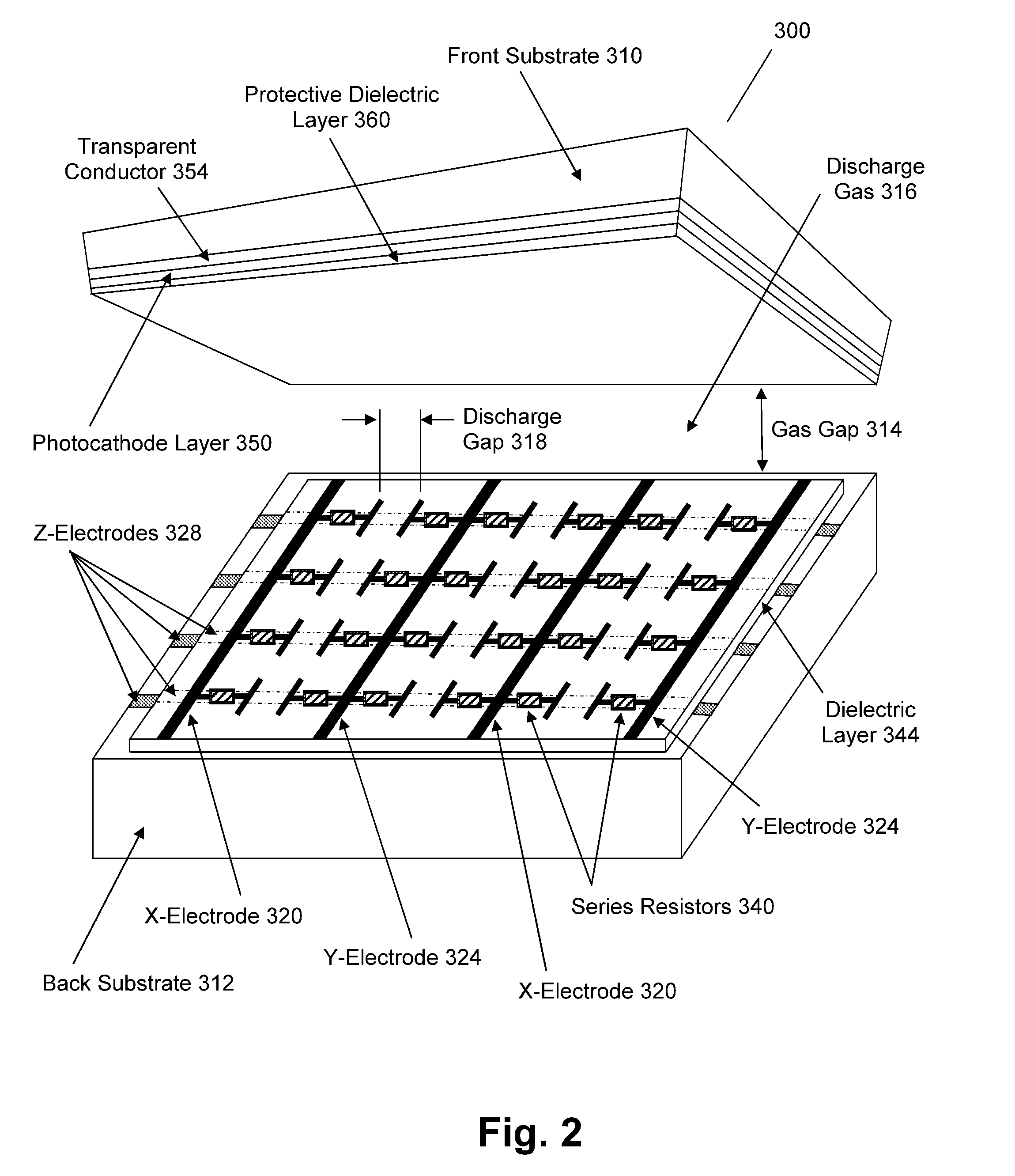
[0019]One embodiment of the present invention is a device that enhances the capability and / or reduces the cost for detecting radiation for ionizing particles and photons, as well as non-ionizing photons such as “optical” photons. Embodiments do not record the magnitude of a given cell gas discharge as do most prior art detectors that operate in the linear region as proportional devices, but instead operates in the non-linear region with extremely high gain and is able to employ Geiger-Mueller type counting methods in assigning essentially the same value to each event regardless of the cell discharge magnitude. Embodiments of the present invention are therefore inherently digital in nature and can be highly pixelated, can utilize low cost materials and fabrication processes, and are extremely rugged and capable of operating under challenging ambient conditions including high magnetic fields. One embodiment comprises a plasma panel device designed to operate as a high gain, highly pix...


PUM


Abstract

A radiation counting detector includes a first substrate and a second substrate that is generally parallel to first substrate and forms a gap with the first substrate. A gas is contained within the gap. A photocathode layer is coupled to one side of the first substrate and faces the second substrate. A first electrode is coupled to the second substrate and a second electrode is electrically coupled to the first electrode. A first impedance is coupled to the first electrode and a second impedance is coupled to the second electrode. A power supply is coupled to at least one of the electrodes. A first discharge event detector is coupled to the first impedance and a second discharge event detector is coupled to the second impedance. The radiation counting detector further includes a plurality of pixels, each capable of outputting a gas discharge pulse upon interaction with radiation received from the photocathode. Each gas discharge pulse is counted as having an approximately equal value. The radiation counting detector further includes circuitry for detecting if a gas discharge pulse is output from the pixels, and for counting each gas discharge pulse as an individual event.

Description

RELATED APPLICATIONS[0001]This application claims the benefit of U.S. Provisional Patent Application No. 60 / 854,919, filed Oct. 28, 2006, the specification of which is herein incorporated by reference, and U.S. Provisional Patent Application No. 60 / 878,508, filed Jan. 4, 2007, the specification of which is herein incorporated by reference.FIELD OF THE INVENTION[0002]Embodiments of the present invention are directed to radiation detection. More particularly, one embodiment of the present invention is directed to a plasma panel based method and apparatus for radiation detection.BACKGROUND INFORMATION[0003]Many useful applications, such as the detection of radioactive material, computer-assisted tomography (“CAT”), digital radiology, optical detectors, etc., rely on the detection of ionizing radiation (e.g., X-ray and gamma-ray photons and / or high energy particles—both neutral and charged) as well as “non-ionizing” photons. Non-ionizing photons, sometimes referred to as “optical” photo...

Claims


Application Information

Patent Timeline
IPC IPC(8): G01T1/18
CPCG01T1/18G01T1/185G01J1/42
Inventor FRIEDMAN, PETER S.
Owner INTEGRATED SENSORS
Learn More