Electrical harmonic suppression system and enclosure for the same

a technology of electric harmonic suppression and enclosure, which is applied in the direction of substation/switching arrangement details, power conversion systems, electrical apparatus, etc., can solve the problems of not being able to fit within the enclosure or being mounted on it, and achieve the effect of simplifying wiring and mounting procedures, being easy to mount, and being easy to attach

Active Publication Date: 2008-09-04
JEFFERSON ELECTRIC LLC
View PDF3 Cites 14 Cited by
  • Summary
  • Abstract
  • Description
  • Claims
  • Application Information

AI Technical Summary

Benefits of technology

[0011]In an electrical distribution system for supplying power from an AC source to an adjustable-speed drive connected in a single-phase manner, the Harmonic Suppression System for substantially eliminating harmonic currents in the supply lines of the system is disclosed. The Harmonic Suppression System comprises a completely-passive parallel resonant circuit having three passive electrical branches, connected in parallel, and the completely-passive parallel resonant circuit having an almost infinite impendence at a 3rd harmonic frequency of the fundamental frequency of the AC source to prevent the formation of the 3rd harmonic frequency so that there is not a 3rd harmonic current to remove or dissipate as heat. The three passive electrical branches comprise a first branch consisting of a capacitor, a second branch consisting of a reactor, and a third branch consisting of a resistor. The completely-passive parallel resonant circuit is electrically connected to at least one supply line, whereby the Harmonic Suppression System renders the electrical distribution system free of the 3rd harmonic frequency, both toward the existing drive and back to the AC source. The completely passive parallel resonant circuit is in series with one or more of the supply lines.
[0013]Another object of the present invention, in an embodiment where the System is small, is to provide a Harmonic Suppression System and an enclosure for the Harmonic Suppression System, designed for mounting either within the already existing drive enclosure or attached to the outside of the existing drive enclosure. More specifically, the enclosure (i) is simple to mount, using standard fittings and requiring no special tools, (ii) can be easily and quickly attached to the existing drive enclosure by a person with standard electrical skills, with no special training necessary, (iii) contains a pre-mounted terminal block for electrical connections to the existing drive, (iv) is designed to be fastened, with standard hardware, to the outside of the existing drive enclosure and can also be close-nippled to the existing drive enclosure, simplifying wiring and mounting procedures, and / or (v) can be easily fastened with standard hardware to the inside of the existing drive enclosure if the Harmonic Suppression System is mounted internally. For larger Systems for higher-powered drives, enclosures will also be provided, but they will not fit within or be capable of being mounted on the drive enclosure.
[0014]Still another object of the present invention is to provide an enclosure for the Harmonic Suppression System that is weather resistant through use of, among other items, (i) welded seams where necessary to ensure protection of the internal circuitry when the Harmonic Suppression System unit is externally mounted, and / or (ii) powder coating to ensure resistance to rusting when the Harmonic Suppression System is externally mounted on or around the existing drive enclosure.

Problems solved by technology

For larger Systems for higher-powered drives, enclosures will also be provided, but they will not fit within or be capable of being mounted on the drive enclosure.

Method used


Image

  • Electrical harmonic suppression system and enclosure for the same
  • Electrical harmonic suppression system and enclosure for the same
  • Electrical harmonic suppression system and enclosure for the same

Examples


Embodiment Construction

[0020]The invention will now be described in detail in relation to a preferred embodiment and implementation thereof which is exemplary in nature and descriptively specific as disclosed. As is customary, it will be understood that no limitation of the scope of the invention is thereby intended. The invention encompasses such alterations and further modifications in the illustrated apparatus and method, and such further applications of the principles of the invention illustrated herein, as would normally occur to persons skilled in the art to which the invention relates.

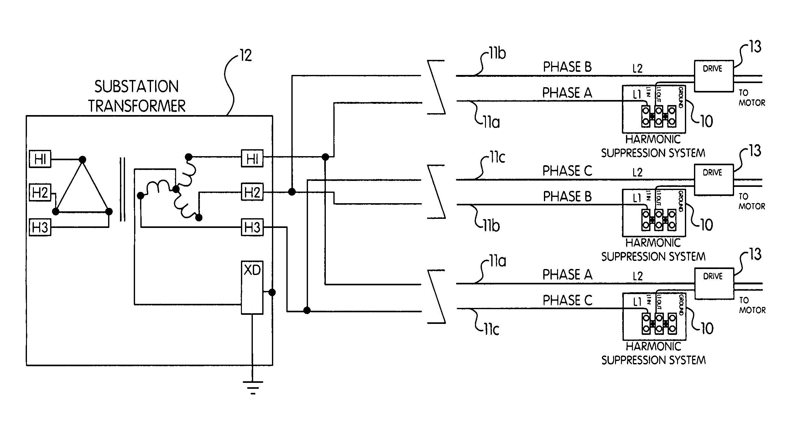
[0021]FIG. 1 shows a circuit schematic of one embodiment of the Harmonic Suppression System 10 according to the present invention. The Harmonic Suppression System 10 is completely passive and preferably comprises, a reactor 1, a capacitor 2, and a resistor 3 connected in parallel, and is tuned to the 3rd harmonic of the AC power source frequency. More specifically, in an electrical distribution system for supplying po...


PUM


Abstract

In an electrical distribution system for supplying power from an AC source to an adjustable-speed drive connected in a single-phase manner, a device for substantially eliminating harmonic currents in the supply lines of said system. The device includes a completely-passive parallel resonant circuit having three passive electrical branches connected in parallel and also having an almost infinite impendence at a third harmonic frequency of a fundamental frequency of said AC source to prevent the formation of only said third harmonic frequency so that there is no third harmonic current to remove or dissipate as heat. The three passive electrical branches comprise a first branch consisting of a capacitor, a second branch consisting of a reactor, and a third branch consisting of a resistor. The parallel resonant circuit is electrically connected to at least one supply line.

Description

PRIORITY[0001]This application hereby claims priority to provisional patent application Ser. No. 60 / 901,599, filed on Feb. 15, 2007.FIELD OF THE INVENTION[0002]The present invention generally relates to an electrical harmonic suppression System and enclosure for the same and more particularly relates to a harmonic suppression System that has application in a remote location, such as a gas well site, and a weatherproof, durable, and easily installed enclosure for the same.BACKGROUND OF THE INVENTION[0003]With the rise in natural gas prices attention is being focused on new sources of energy. It has been known for many years that there is a large quantity of natural gas associated with underground coal beds. Due to the porous nature of coal, many times the volume of gas per cubic foot of solid material is more readily available when compared to gas found in rocky formations. The gas is under high pressure, and is associated with large quantities of water which also permeate the coal b...

Claims


Application Information

Patent Timeline
Patent Type & Authority Applications(United States)
IPC IPC(8): H02M1/12H02B1/00
CPCH02M1/126
Inventor LOWENSTEIN, MICHAEL Z.
Owner JEFFERSON ELECTRIC LLC
Why Eureka
Try Eureka