Inner rotor type permanent magnet excited transverse flux motor

a technology of excited transverse flux and rotor, which is applied in the direction of rotating magnets, magnetic circuit rotating parts, synchronous machines with stationary armatures, etc., can solve the problems of not easy to manufacture the same, adopt a laminated structure suitable for the three-dimensional structure, etc., to reduce noise and vibration, reduce iron loss, and increase output power and efficiency

Active Publication Date: 2008-09-04
KOREA ELECTROTECH RES INST
View PDF5 Cites 103 Cited by
  • Summary
  • Abstract
  • Description
  • Claims
  • Application Information

AI Technical Summary

Benefits of technology

[0010]Accordingly, the present invention has been made in an effort to solve the above-described problems, and an object of the present invention is to provide an inner rotor type permanent magnet excited transverse flux motor, in which a powdered iron core press-molded using a mold and a laminated structure in an axial direction or in a radial shape are applied to stator and rotor iron cores, thus facilitating the production of a transverse flux motor, reducing iron loss, increasing output power and efficiency, and reducing noise and vibration.

Problems solved by technology

However, the conventional transverse flux motor has problems in that, since it has a three-dimensional magnetic flux flow, it is not easy to manufacture the same, compared with the longitudinal flux motor, and it is difficult to adopt a laminated structure suitable for the three-dimensional magnetic flux flow, and such problems arise in a linear motor rather than a rotary motor.

Method used


Image

  • Inner rotor type permanent magnet excited transverse flux motor
  • Inner rotor type permanent magnet excited transverse flux motor
  • Inner rotor type permanent magnet excited transverse flux motor

Examples


Embodiment Construction

[0057]Hereinafter, preferred embodiments in accordance with the present invention will be described with reference to the accompanying drawings. The preferred embodiments are provided so that those skilled in the art can sufficiently understand the present invention, but can be modified in various forms and the scope of the present invention is not limited to the preferred embodiments.

[0058]First, an inner rotor type permanent magnet excited transverse flux motor in accordance with a preferred embodiment of the present invention will be described with reference to FIGS. 1 to 9.

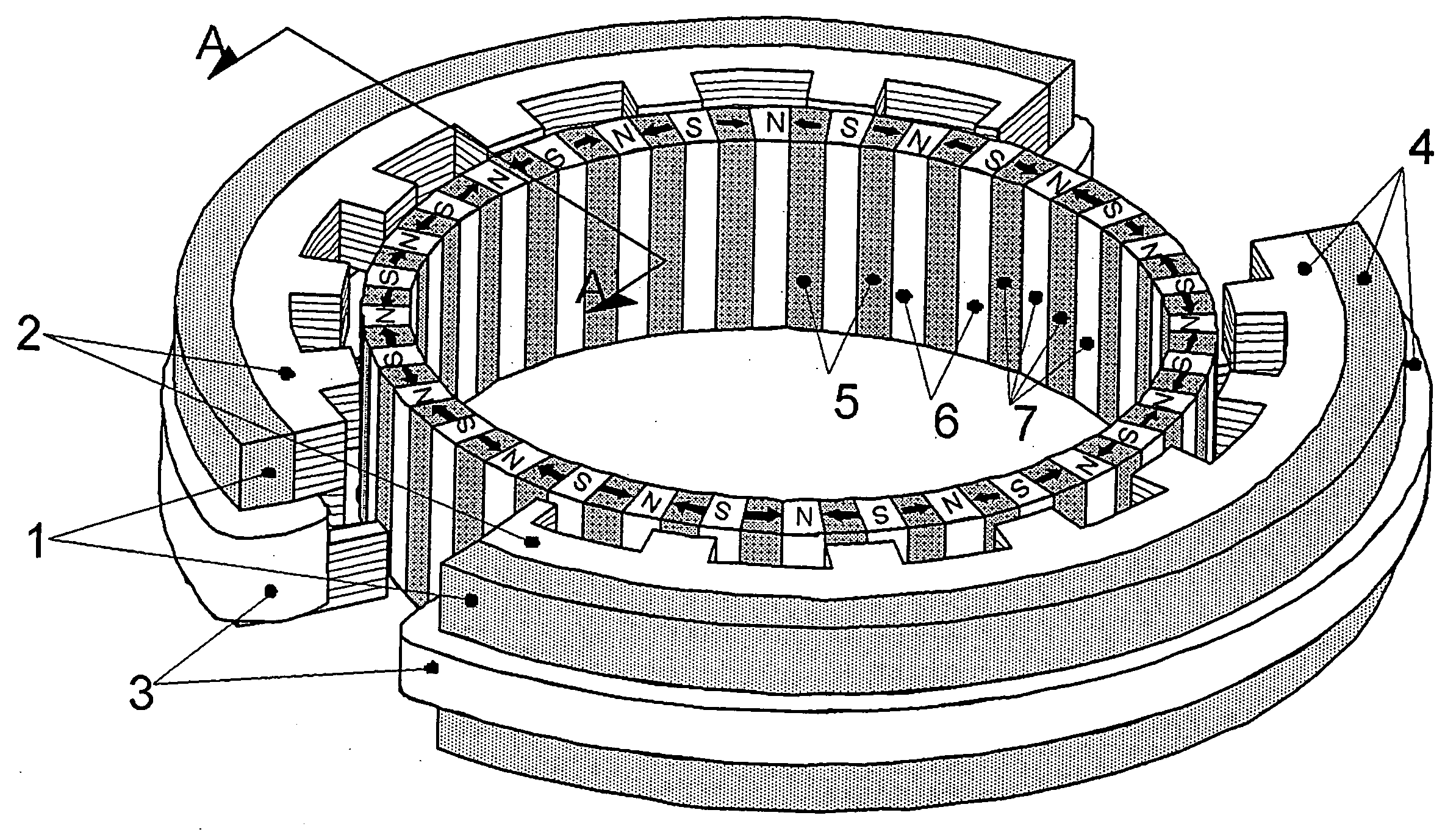
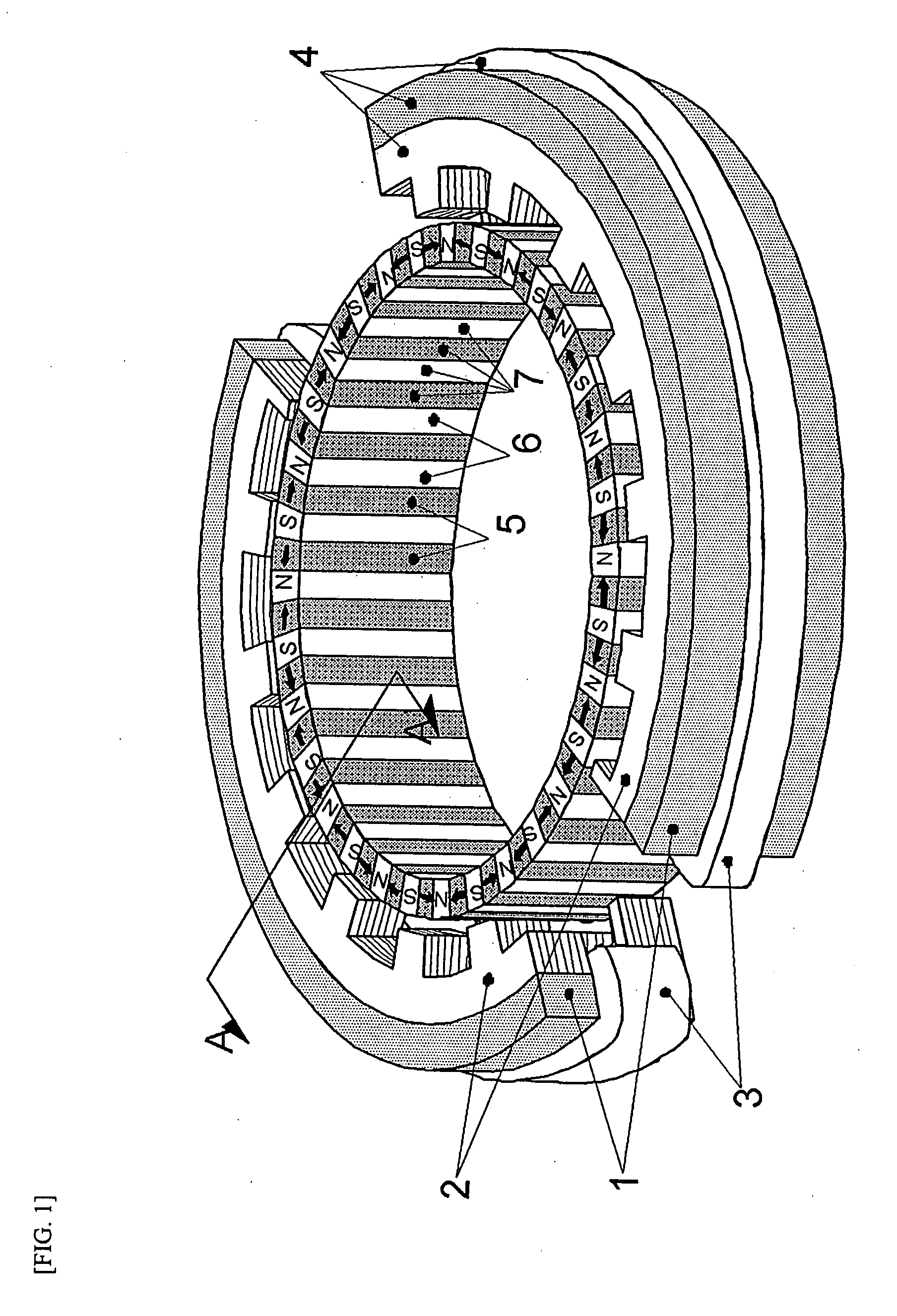
[0059]FIG. 1 is a perspective view illustrating an inner rotor type permanent magnet excited transverse flux motor with a segmented stator in accordance with a preferred embodiment of the present invention.

[0060]As shown in FIG. 1, the inner rotor type permanent magnet excited transverse flux motor generally comprises a segmented stator 4 and a rotor 7.

[0061]The segmented stator 4 includes a segmented stator p...


PUM


Abstract

Disclosed herein is an inner rotor type permanent magnet excited transverse flux motor, in which a laminated structure in an axial direction or in a radial shape is applied to a stator iron core so as to employ a small amount of permanent magnets compared with a conventional outer rotor type permanent magnet excited transverse flux motor, thus providing high output power, increasing the efficiency of power generation, and reducing noise and vibration.
For this, the present invention provides an inner rotor type permanent magnetic excited transverse flux motor comprising: a stator including a stator powdered iron core press-molded using a mold, a stator laminated iron core laminated on upper and lower layer portions of the circumference of the stator powdered iron core at regular intervals, and a stator winding which winds the segmented stator powdered iron core in which a current flows is wound between the intervals; and a rotor in which a rotor permanent magnet and a rotor powdered iron core are arranged alternately to face each other.

Description

CROSS-REFERENCE TO RELATED APPLICATION[0001]This application claims the benefit of Korean Patent Application No. 10-2006-0135779, filed on Dec. 28, 2006, the entire disclosure of which is hereby incorporated by reference.BACKGROUND OF THE INVENTION[0002]1. Field of the Invention[0003]The present invention relates to an inner rotor type permanent magnet excited transverse flux motor and, more particularly, to an inner rotor type permanent magnet excited transverse flux motor, in which a laminated structure in an axial direction or in a radial shape is applied to a stator iron core so as to employ a small amount of permanent magnets compared with a conventional outer rotor type permanent magnet excited transverse flux motor, thus providing high output power, increasing the efficiency of power generation, and reducing noise and vibration.[0004]2. Description of Related Art[0005]In general, a motor is a device that converts electrical energy into mechanical energy and basically requires...

Claims


Application Information

Patent Timeline
Patent Type & Authority Applications(United States)
IPC IPC(8): H02K1/12H02K1/27
CPCH02K21/145H02K2213/12H02K2201/12H02K21/16H02K1/12
Inventor KANG, DO HYUNCHANG, JUNG HWANLEE, JI YOUNGKIM, JI WONCHUNG, SHI UK
Owner KOREA ELECTROTECH RES INST
Why Eureka
Try Eureka