Holographic Sensors and Their Uses

Inactive Publication Date: 2008-09-04
GUNMA UNIVERSITY +4
View PDF4 Cites 0 Cited by
  • Summary
  • Abstract
  • Description
  • Claims
  • Application Information

AI Technical Summary

Benefits of technology

[0011]The method of the present invention allows the three-dimensional position of a hologram in a holographic sensor to be determined and hence the wavelength of diffracted light to be measured at a known diffraction angle. In practice, this means that the concentration or intensity of a stimulant to which the holographic sensor is sensitive can be determined quickly and easily in a wi

Problems solved by technology

This can be difficult and time-consuming and, in practice, is usually carried out in a laboratory where the position of the hologram can be well controlled on an optic

Method used


Image

  • Holographic Sensors and Their Uses
  • Holographic Sensors and Their Uses
  • Holographic Sensors and Their Uses

Examples


Embodiment Construction

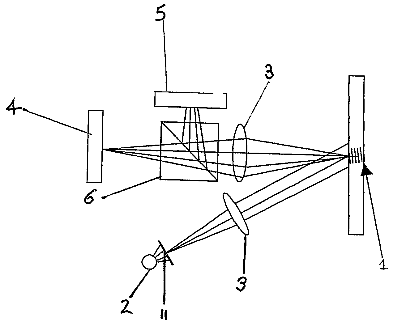
[0019]In this specification, the term holographic sensor means a holographic element made up from a support medium with a hologram therein. The hologram can be dispersed in or on part of or throughout the bulk. The support medium interacts with a stimulant resulting in a variation of a physical property of the medium which induces a change in the optical characteristic of the hologram.

[0020]The hologram is a three-dimensional distribution (modulation) pattern which is a physical record of an original interference pattern and can be generated by the diffraction of light. Peaks of modulation are referred to as “fringes” and can be formed from silver grains. The hologram acts as a diffraction grating to filter light in accordance with the Bragg equation and variations in the physical properties of the support due to the interaction with a stimulant can alter the fringe separation, leading to a change in wavelength at a fixed angle of incidence or change in intensity at monochromic peak...


PUM


Abstract

A method of analysing a holographic sensor (1) comprising a hologram, wherein interaction of the holographic sensor with a stimulant causes a change in the wavelength of diffracted light from the hologram, comprises the steps of: a) viewing light diffracted by the hologram and specular reflections in an image plane of a lens; b) viewing light diffracted by the hologram and specular reflections in a focal plane of the lens or of a different lens; c) interacting the holographic sensor with a stimulant and determining the change in the wavelength of diffracted light; and d) using the information obtained to determine a property of the stimulant or of the sensor. A device suitable for use in such a method comprises a lens (3), means for detecting light in the image (4) and focal (5) planes of the lens, and image-processing software.

Description

FIELD OF THE INVENTION[0001]This invention relates to a method for analysing a holographic sensor and to a device for use in such a method.BACKGROUND OF THE INVENTION[0002]Holographic sensors are known, and are disclosed in, inter alia, WO95 / 26499 and WO99 / 63408. They comprise a holographic support medium which has, disposed throughout its volume, a hologram. Such holographic sensors are capable of detecting an analyte when the support medium interacts with the analyte, resulting in a variation of a physical property of the medium. This variation induces a change in an optical characteristic of the holographic element, such as its polarisability, reflectance, refractance or absorbance. The change in optical characteristics may be visible with a human eye or may be detected using a spectrometer if the position of the hologram is well controlled.[0003]When using a spectrometer to make measurements on a hologram, the spectrometer must be aligned with the surface of the hologram. This c...

Claims


Application Information

Patent Timeline
IPC IPC(8): G01J3/00G01N21/47G01N21/77
CPCG01N21/4788G03H1/22G03H1/0011G01N21/77
Inventor CREASEY, CHRISTOPHER
Owner GUNMA UNIVERSITY
Why Eureka
Try Eureka