
Wavelength displacement correcting system

a technology of wavelength displacement and correcting system, which is applied in the direction of optical radiation measurement, instruments, spectrometry/spectrophotometry/monochromators, etc., can solve the problems of change in grating constant, unavoidable wavelength displacement, and inability to distinguish a wavelength displacement of light emitting diodes from a change in dispersion width

Inactive Publication Date: 2008-09-04
KONICA MINOLTA SENSING INC
View PDF3 Cites 11 Cited by
  • Summary
  • Abstract
  • Description
  • Claims
  • Application Information

AI Technical Summary

Benefits of technology

[0008]In view of the above problems residing in the conventional art, it is an object of the present invention to provide a wavelength displacement correcting sys

Problems solved by technology

The plastic molded parts, however, unavoidably undergo a change with time and / or under heat after the molding, with the result that a wavelength displacement is unavoidable.
In D1, however, it is impossible to distinguish a wavelength displacement of the light emitting diode from a change in dispersion width, because in both of the cases, the wavelength displacement with respect to the second-order beam is twice as large as the wavelength displacement with respect to the first-order beam.
Accordingly, D1 fails to correct a change in dispersion width resulting from a change in grating constant, which may be serious in the case where a plastic diffraction grating subjected to a large thermal expansion is used.
Accordingly, D2 not only fails to cope with a non-uniform temperature change but also fails to cope with a wavelength displacement resulting from a cause other than the temperature change such as a change with time.

Method used


Image

  • Wavelength displacement correcting system
  • Wavelength displacement correcting system
  • Wavelength displacement correcting system

Examples


Embodiment Construction

[0017]In the following, an embodiment of the invention is described referring to the drawings. The elements with the same reference numerals throughout the drawings have the same arrangement, and repeated description thereof is omitted herein.

[0018](Overall Description on Wavelength Displacement Correcting System)

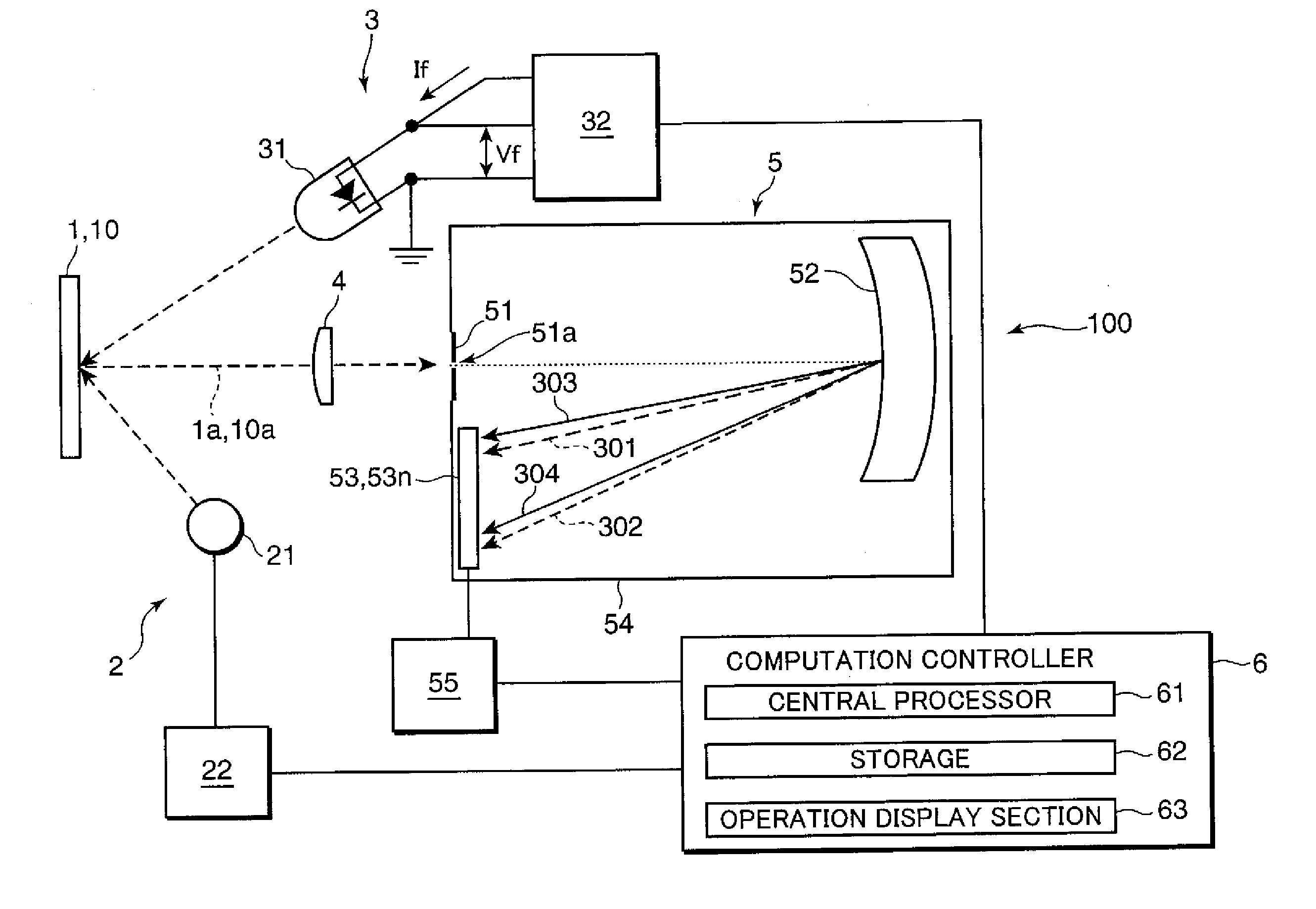
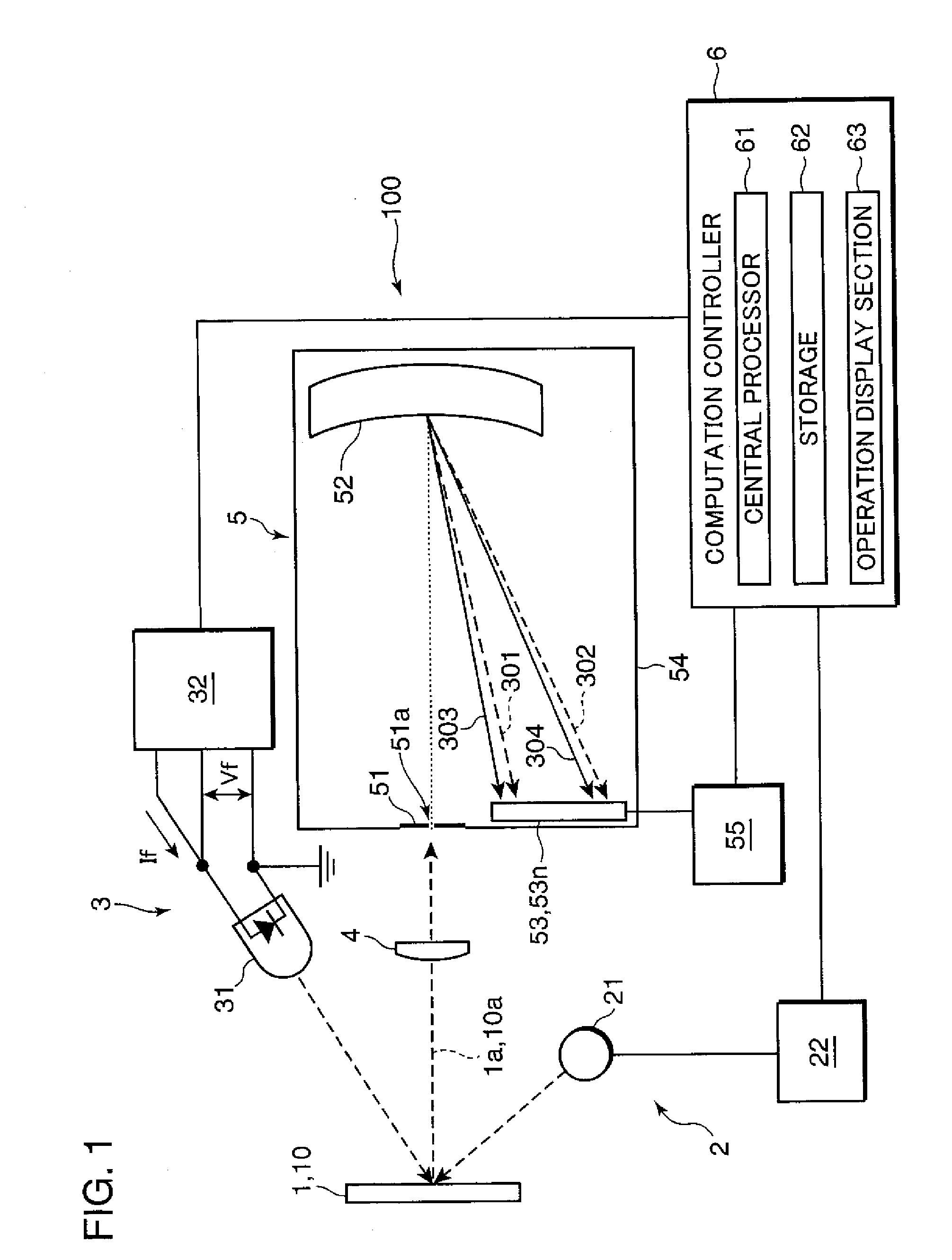
[0019]FIG. 1 is a block diagram showing an example of a wavelength displacement correcting system embodying the invention. Referring to FIG. 1, a wavelength displacement correcting system 100 includes a measurement illuminator 2, a correction illuminator 3, a measurement optics 4, a polychromator 5, and a computation controller 6.

[0020]The measurement illuminator 2 includes an incandescent lamp 21 as a light source, and a lamp controller 22 for controlling on / off operations of the incandescent lamp 21. The measurement illuminator 2 is adapted to illuminate a sample 1 or a white reference sample 10 by the incandescent lamp 21. In this embodiment, the measurement illuminator ...


PUM


Abstract

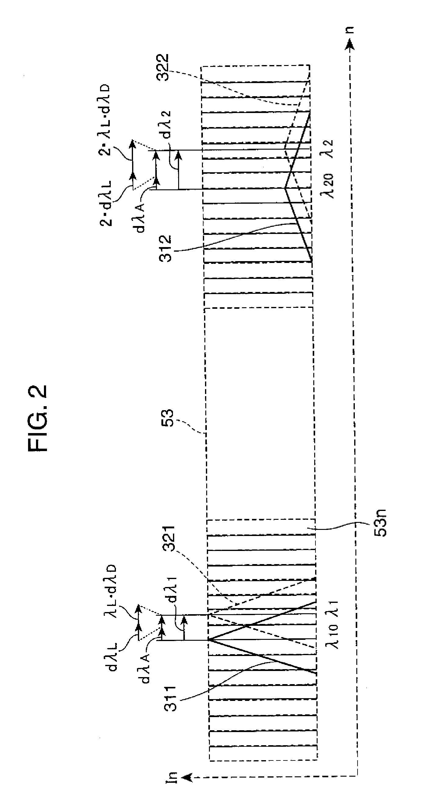
In a wavelength displacement correcting system and method of the invention, a monochromatic beam from a light emitting diode driven by a constant current is incident through an incident slit of a spectral device. The incident beam is diffracted on a diffraction grating to form a dispersed light image, and information relating to the dispersed light image of the incident slit is outputted from the spectral device. A wavelength displacement amount of the monochromatic beam is calculated, using a forward voltage value corresponding to the constant current, and a forward voltage initial value. Wavelength displacement amounts of at least two diffracted beams are calculated, using output values of the at least two diffracted beams, and diffracted beam output initial values with respect to the dispersed light image. A dispersion width displacement amount of the spectral device is calculated, using the calculated wavelength displacement amount of the monochromatic beam, and the calculated wavelength displacement amounts of at least two diffracted beams, whereby a wavelength displacement of the spectral device is corrected.

Description

[0001]This application is based on Japanese Patent Application No. 2007-21956 filed on Jan. 31, 2007, the contents of which are hereby incorporated by reference.BACKGROUND OF THE INVENTION[0002]1. Field of the Invention[0003]The present invention relates to a wavelength displacement correcting system for use in a polychromator, particularly for use in a polychromator provided with plastic molded parts to correct a wavelength displacement of the polychromator with time and / or under heat.[0004]2. Description of the Related Art[0005]Conventionally, there has been popularly used a polychromator, as a spectral device for use in a spectral apparatus such as a spectrocolorimeter or a spectroradiometer. The polychromator is constructed in such a manner that wavelength dispersed beams by diffraction on a diffraction grating are simultaneously received on a light receiving array. Considering production cost reduction, it is desirable to use plastic molded parts as primary elements of the poly...

Claims


Application Information

Patent Timeline
IPC IPC(8): G01J3/28
CPCG01J3/02G01J3/027G01J2003/2866G01J3/28G01J3/2803G01J3/18
Inventor IMURA, KENJIMATSUMOTO, TAKESHI
Owner KONICA MINOLTA SENSING INC
Learn More