Method of fabricating semiconductor wafer

a technology of semiconductor wafers and manufacturing methods, applied in the field of semiconductor wafer manufacturing, can solve the problems of inflicting damage on the silicon lattice of bulk wafers, consuming a lot of power of semiconductor devices, and operating at a relatively low speed,

Inactive Publication Date: 2008-09-04
SAMSUNG ELECTRONICS CO LTD
View PDF4 Cites 196 Cited by
  • Summary
  • Abstract
  • Description
  • Claims
  • Application Information

AI Technical Summary

Benefits of technology

[0015]In some embodiments of the present invention, the preparation of the subsidiary wafer having at least one single crystalline pattern may farther include forming a deposition preventing pattern on the subsidiary wafer to expose an upper region of the single crystalline pattern. The deposition preventing pattern may cover a sidewall of t

Problems solved by technology

Since a semiconductor device using a bulk wafer as a substrate may have a large parasitic capacitance between the bulk wafer and a conductive layer disposed thereon, the semiconductor device may consume a lot of power and may operate at comparatively low speed.
However, forming a single-crystalline silicon layer on an insulating layer using a conventional deposition technique may be

Method used


Image

  • Method of fabricating semiconductor wafer
  • Method of fabricating semiconductor wafer
  • Method of fabricating semiconductor wafer

Examples


Embodiment Construction

[0029]The present invention is described more fully hereinafter with reference to the accompanying drawings, in which example embodiments of the invention are shown. The present invention may, however, be embodied in many different forms and should not be construed as limited to the example embodiments set forth herein. Rather, these example embodiments are provided so that this disclosure will be thorough and complete, and will fully convey the scope of the present invention to those skilled in the art. In the drawings, the sizes and relative sizes of layers and regions may be exaggerated for clarity.

[0030]It will be understood that when an element or layer is referred to as being “on,”“connected to,”“coupled to” or “responsive to” another element or layer, it can be directly on, connected, coupled or responsive to the other element or layer or intervening elements or layers may be present. In contrast, when an element is referred to as being “directly on,”“directly connected to,”“...


PUM


Abstract

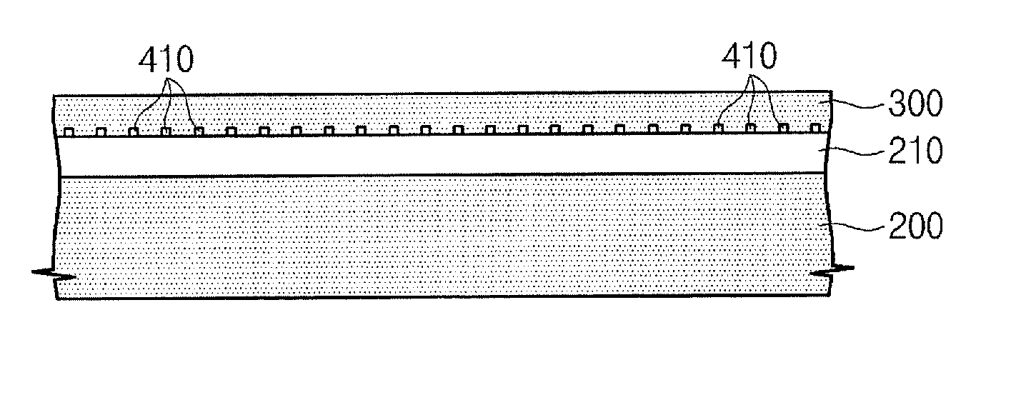
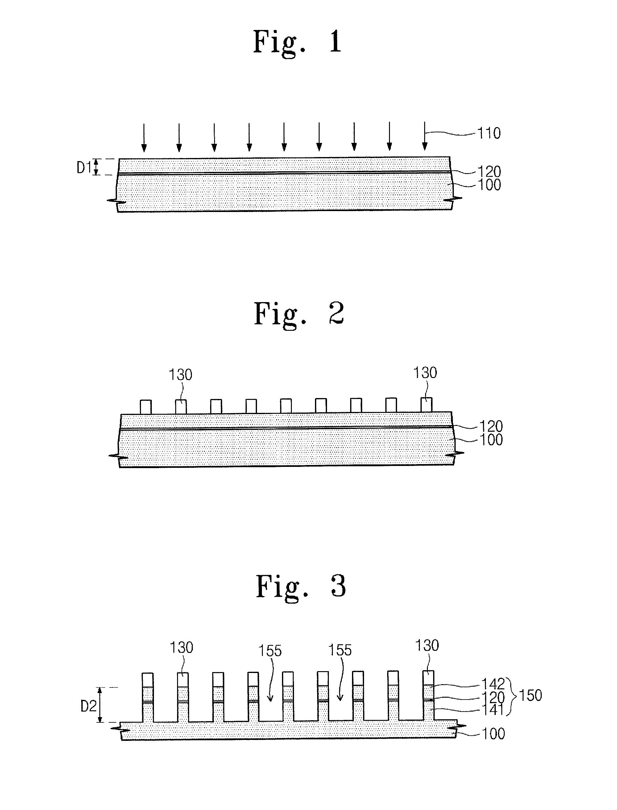
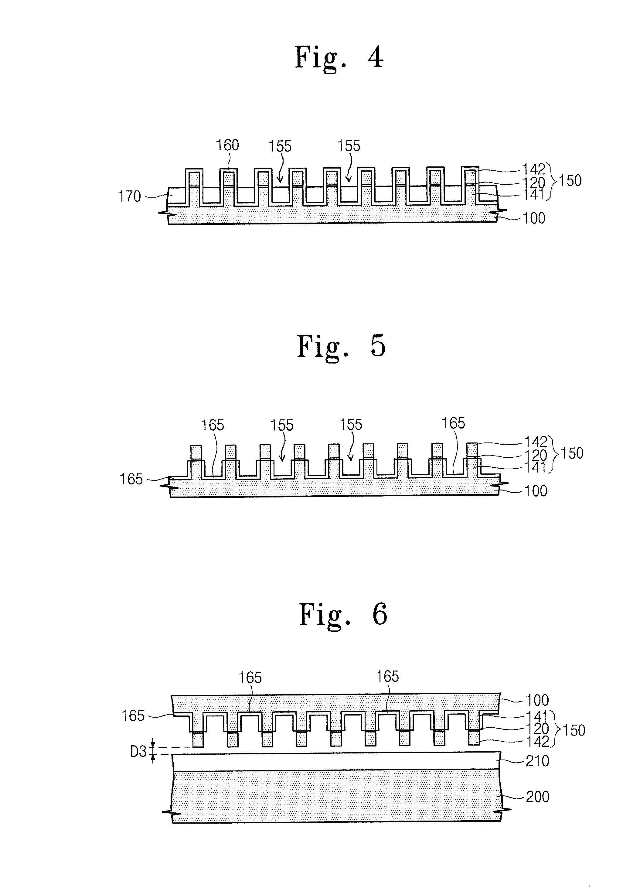
Provided is a method of fabricating a semiconductor wafer. The method includes preparing a substrate wafer having a non-single-crystalline thin layer; disposing at least one single crystalline pattern adjacent to the non-single-crystalline thin layer on the substrate wafer; and forming a material layer contacting the single crystalline pattern on the non-single-crystalline thin layer.

Description

[0001]This application claims priority to Korean Patent Application No. 10-2007-0021075, filed on Mar. 2, 2007, the disclosure of which is hereby incorporated herein by reference.FIELD OF THE INTENTION[0002]The present invention relates generally to semiconductors and, more particularly, semiconductor manufacturing.BACKGROUND OF THE INVENTION[0003]Since a semiconductor device using a bulk wafer as a substrate may have a large parasitic capacitance between the bulk wafer and a conductive layer disposed thereon, the semiconductor device may consume a lot of power and may operate at comparatively low speed. In order to overcome these drawbacks, a method of sequentially stacking an insulating layer and a silicon layer on a bulk wafer using silicon-on-insulator (SOI) techniques has been proposed.[0004]Meanwhile, the silicon layer should have a single crystalline structure so that the silicon layer can be used as a channel region of a transistor. However, forming a single-crystalline sili...

Claims


Application Information

Patent Timeline
IPC IPC(8): H01L21/36
CPCH01L21/76254H01L21/0237H01L21/02639H01L21/0262H01L21/02433H01L21/20H01L27/12
Inventor PARK, YOUNG-SOOLIM, YOUNG-SAMKIM, YOUNG-NAMBAE, DAE-LOKCHOI, JOON-YOUNGKIM, GI-JUNG
Owner SAMSUNG ELECTRONICS CO LTD
Why Eureka
Try Eureka