Therapeutic micro-vibration device

a technology of micro-vibration and therapeutic devices, which is applied in the field of medical therapy devices, can solve the problems of not using or suggesting coordination and integrative merging in prior art devices, and many prior art devices are large and expensive, and achieve the effect of enhancing pain relief and increasing blood flow to affected areas

Inactive Publication Date: 2008-09-04
MILNE ROBERT +1
View PDF35 Cites 48 Cited by
  • Summary
  • Abstract
  • Description
  • Claims
  • Application Information

AI Technical Summary

Benefits of technology

[0011]In one aspect, the device includes a motor that produces micro-vibrations and audible signals and drives one or more permanent magnets or electromagnets and one or more light sources. Importantly, the motor produces a very small electromagnetic field so as not to interfere with the magnetic flux generated by the one or more permanent magnets or electromagnets. An applicator end of the device is placed in contact with, or proximate to, an area of the body suffering from pain or related affliction. During clinical trials, the combination of the magnetic, photon, vibration and sound technologies proved to provide pain relief in very short time periods.
[0012]In another aspect, a therapeutic module for relieving pain and providing a curative healing effect is provided. The therapeutic module includes a motor for rotating at least one magnet to generate a magnetic field, micro-vibrations and audible acoustic tones. A shaft couples the at least one magnet to the motor. The at least one magnet is coupled to the shaft in an offset configuration with respect to a centerline of the shaft thereby generating micro-vibrations in the form of oscillating inertial loads. The therapeutic module includes a light source for generating a photonic light field in an optical light spectrum.
[0018]Magnetic therapy has been used for thousands of years around the world. Countries, including China, Japan, Russia, France and England have produced many documents on the subject. Around the world, magnetic therapy is considered a safe approach to healing. In the United States however, magnetic therapy is not generally considered a viable approach to healing. Nonetheless, some medical doctors in the United States have reported the use of static magnets to increase the speed at which bone fractures heal.
[0021]It is well known in the art that vibratory massage provides mechanical stimulation of tissues to increase blood flow to affected areas and enhance pain relief.

Problems solved by technology

There is, however, no prior art that discloses or suggests coordination and integrative merging of the above-identified technologies in such a manner to bring about a synergistic enhancement of all four technologies.
Many of the prior art devices are large and expensive and may require a patient to lie down on the device for several hours.
None of the prior art devices utilize or suggest the use of mechanical micro-vibration, photon, sonic, and magnetic technologies in a handheld device which provides pain relief in a short period of time (e.g., seconds) from application.

Method used


Image

  • Therapeutic micro-vibration device
  • Therapeutic micro-vibration device
  • Therapeutic micro-vibration device

Examples


first embodiment

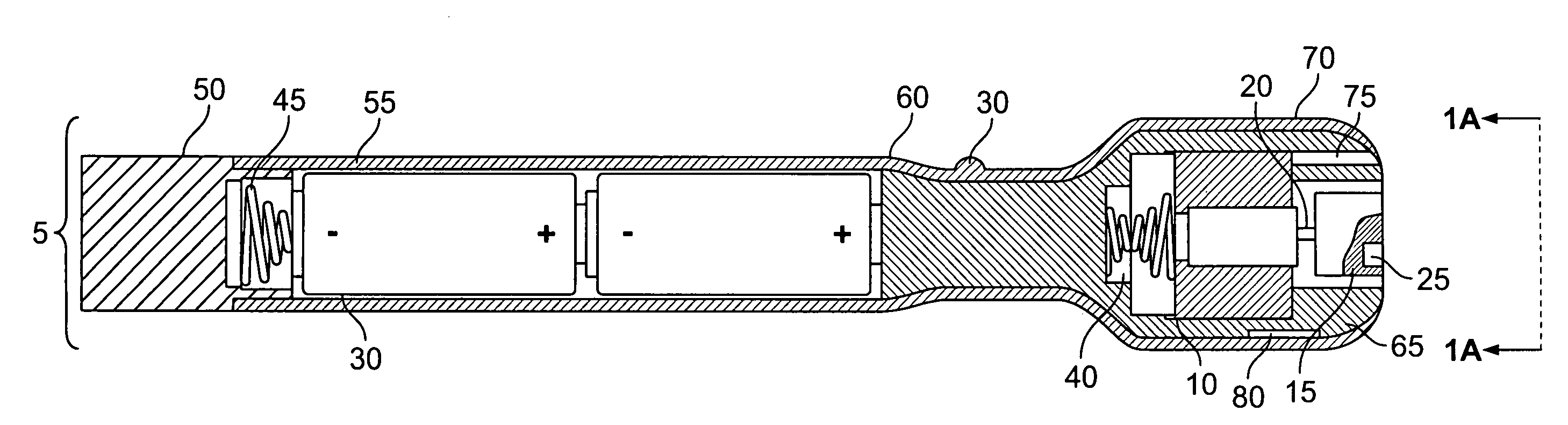
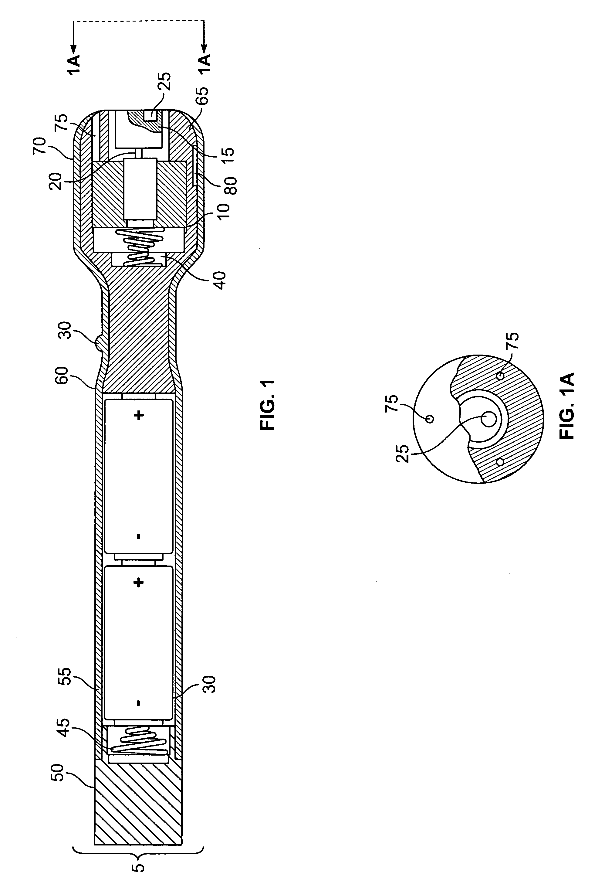
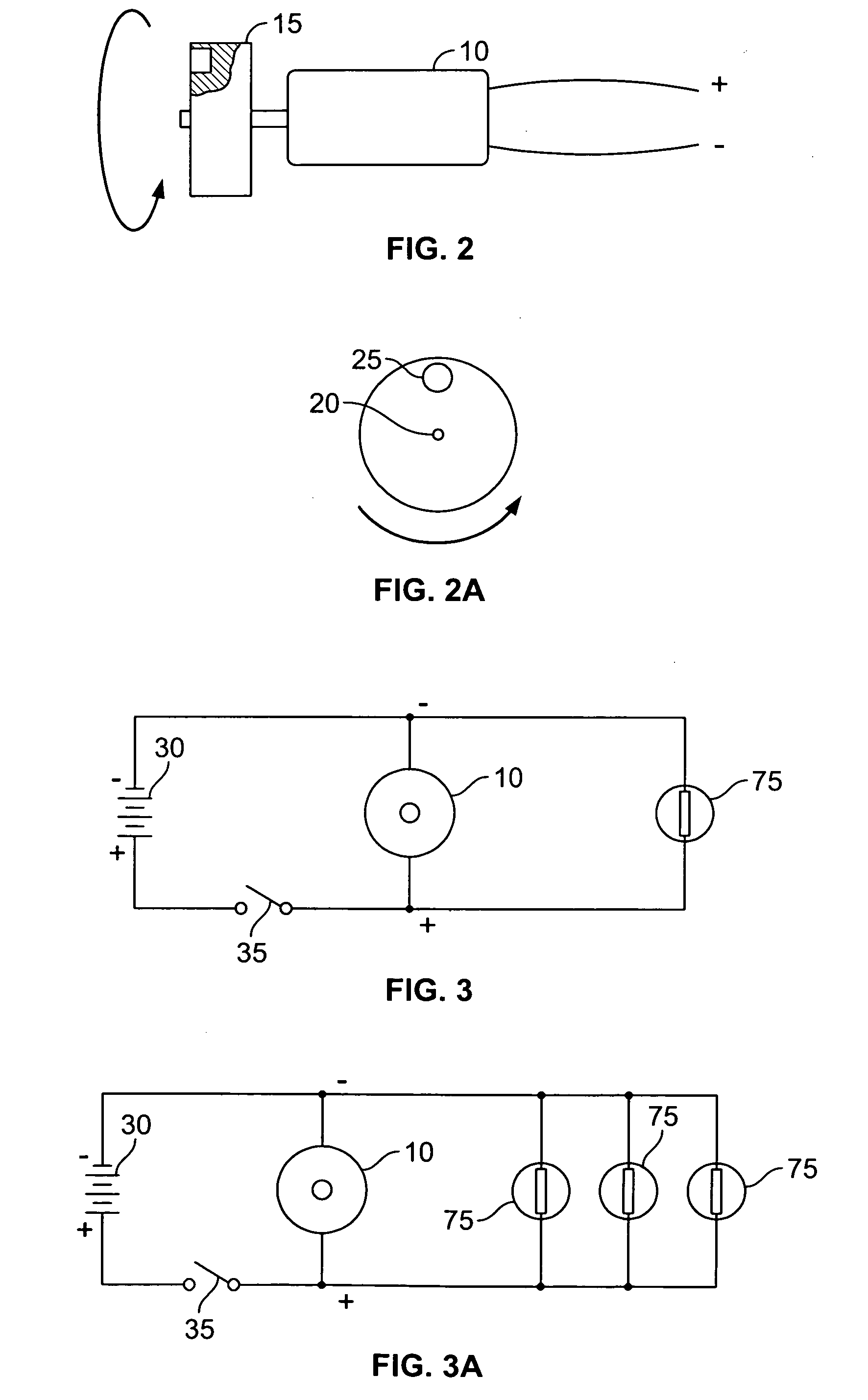
[0038]the present invention is illustrated in FIGS. 1-3. The therapeutic device 5 comprises an electric motor 10 with a magnet holding fixture 15 attached to a motor shaft 20. Permanent magnet or electromagnet 25 is attached and held in place within holding fixture 15. As the permanent magnet or electromagnet 25 is connected to the shaft 20 in an offset manner, permanent magnet or electromagnet 25 is rotatably driven about the centerline of motor shaft 20 by motor 10. Depending on the use, the magnet 25 may be rotated at a constant or alternating rate of 500 to 150,000 revolutions per minute. Ideally, the intensity of the generated magnetic field is less than ten gauss. Importantly, the motor 10 should produce only a very small electromagnetic field so as not to interfere with the magnetic flux generated by the one or more permanent magnets or electromagnets 25. For example, the motor 10 may produce a magnetic or electromagnetic field with an intensity of less than 1% of that genera...

embodiment 65

[0039]The motor 10 is powered by batteries 30 in response to electrical on-off switch 35 being turned on. As shown, the positive voltage (+) from batteries 30 flows through electrical conductor 40 to motor 10 and the negative voltage (−) flows through electrical conductor 45, battery holding cap 50, device enclosure 55, switch holding enclosure 60, enclosure embodiment 65 and motor holding fixture 70 to motor 10.

[0040]Photonic light is produced by one or more light sources 75, such as light bulbs. A laser or a light emitting diode may be used as well. Light sources 75 are electrically energized in a manner similar to motor 10. FIG. 1A shows a cross-section end view which details magnet 25 and multiple light sources 75. The light may fall into a broadband spectrum of light ranging from ultraviolet to infrared with optical light wavelengths ranging from about 1 nanometer (nm) to about 12,000 nm and the light sources 75 are directed into the magnetic field produced by magnet 25.

[0041]T...


PUM


Abstract

A therapeutic device for relieving pain and providing a curative healing effect includes a motor for rotating at least one magnet to generate a magnetic field, micro-vibrations and audible acoustic tones. A shaft couples the at least one magnet to the motor. In one embodiment, the at least one magnet is coupled to the shaft in an offset configuration with respect to a centerline of the shaft thereby generating micro-vibrations in the form of oscillating inertial loads. The therapeutic device includes a light source for generating a photonic light field in an optical light spectrum.

Description

CROSS REFERENCE TO RELATED APPLICATIONS[0001]This is a continuation-in-part application of U.S. application Ser. No. 11 / 121,602, filed May 4, 2005, which is hereby incorporated by reference in its entirety.FIELD OF THE INVENTION[0002]The embodiments of the present invention relate to a medical therapy device that utilizes micro-vibratory massaging action with magnetic and photonic light beam fields, accompanied by sound waves, to induce an increase in cellular energy thereby providing pain reduction and healing in living cells.BACKGROUND OF THE INVENTION[0003]The use of vibrating devices for massaging painful areas on the human body by stimulating blood flow has long been considered beneficial. Photonic light beam therapy, typically utilizing laser beams, for relieving pain and healing anomalous tissue has also been used with varying levels of success. Static and pulsating magnetic field therapy has been used for many years throughout the world with varying levels of success. Sound ...

Claims


Application Information

Patent Timeline
Patent Type & Authority Applications(United States)
IPC IPC(8): A61H1/00
CPCA61H15/0092A61H23/0236A61H23/0263A61H2201/10A61H2201/501A61H7/001A61H2201/5097A61N2/00A61N2005/0644A61N2005/0651A61H2201/5043
Inventor MILNE, ROBERTSPAWR, WALTER J.
Owner MILNE ROBERT
Why Eureka
Try Eureka