Vehicle parking system and method for controlling the same

a technology for parking systems and vehicles, applied in brake systems, friction linings, transportation and packaging, etc., can solve the problems of significant voltage drop in increase the magnitude of the electric current to be supplied from the power supply unit, etc., and achieve the effect of reducing the number of components and reducing the cos

Active Publication Date: 2008-09-11
TOYOTA JIDOSHA KK
View PDF5 Cites 23 Cited by
  • Summary
  • Abstract
  • Description
  • Claims
  • Application Information

AI Technical Summary

Benefits of technology

[0030]In the first aspect of the invention, the parking lock mechanism may include a shift position-linked control unit that changes, by operating the first electromagnetically-driven actuator, the shift position of an automatic transmission of the vehicle to Park, and changes the state from the state in which the rotation of the drive power transfer shaft, which extends between an output shaft of the automatic transmission and the wheel is p

Problems solved by technology

If both of the two electric motors are started based on the operation command and the times at which the magnitudes of the striking currents reach their peaks coincide with each

Method used


Image

  • Vehicle parking system and method for controlling the same
  • Vehicle parking system and method for controlling the same
  • Vehicle parking system and method for controlling the same

Examples


Embodiment Construction

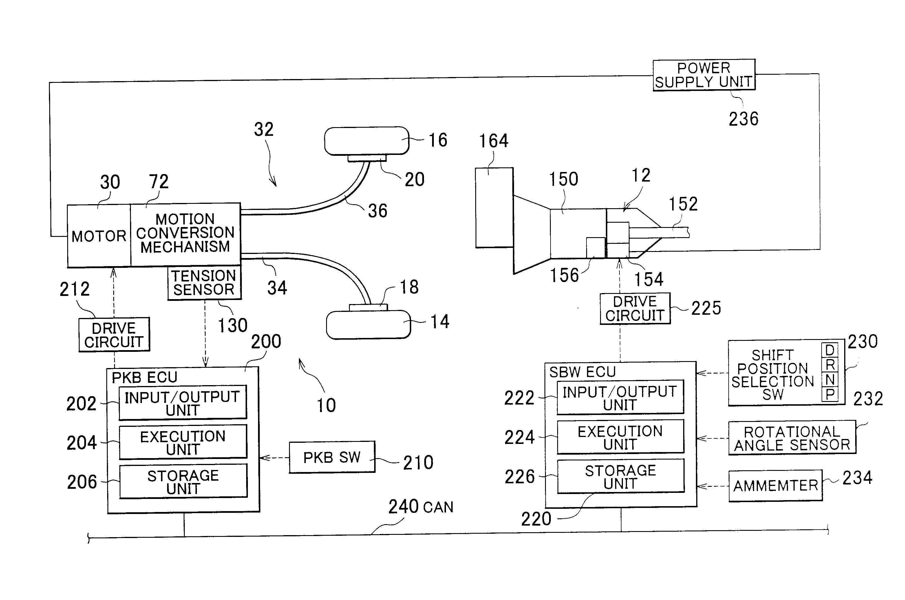
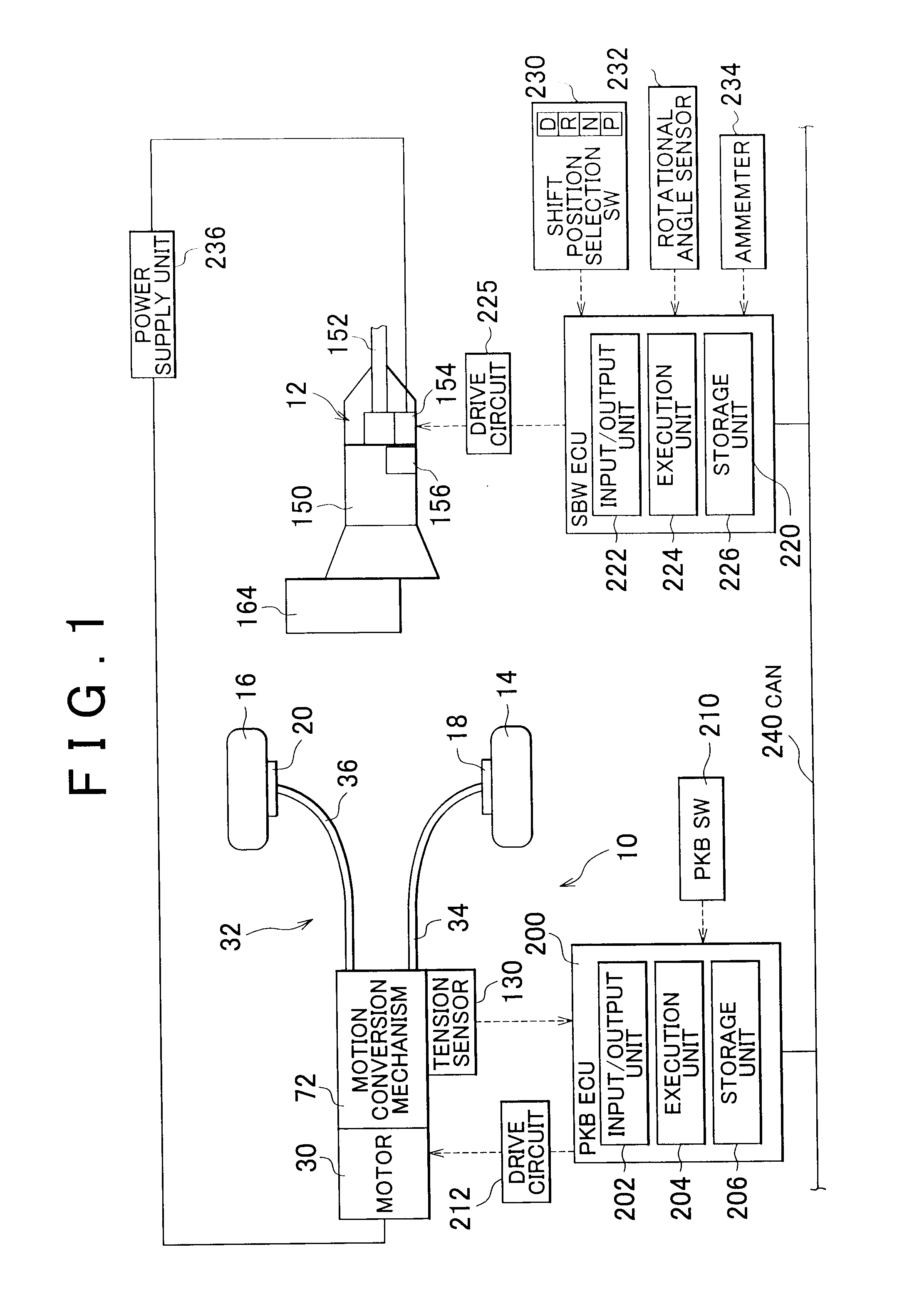
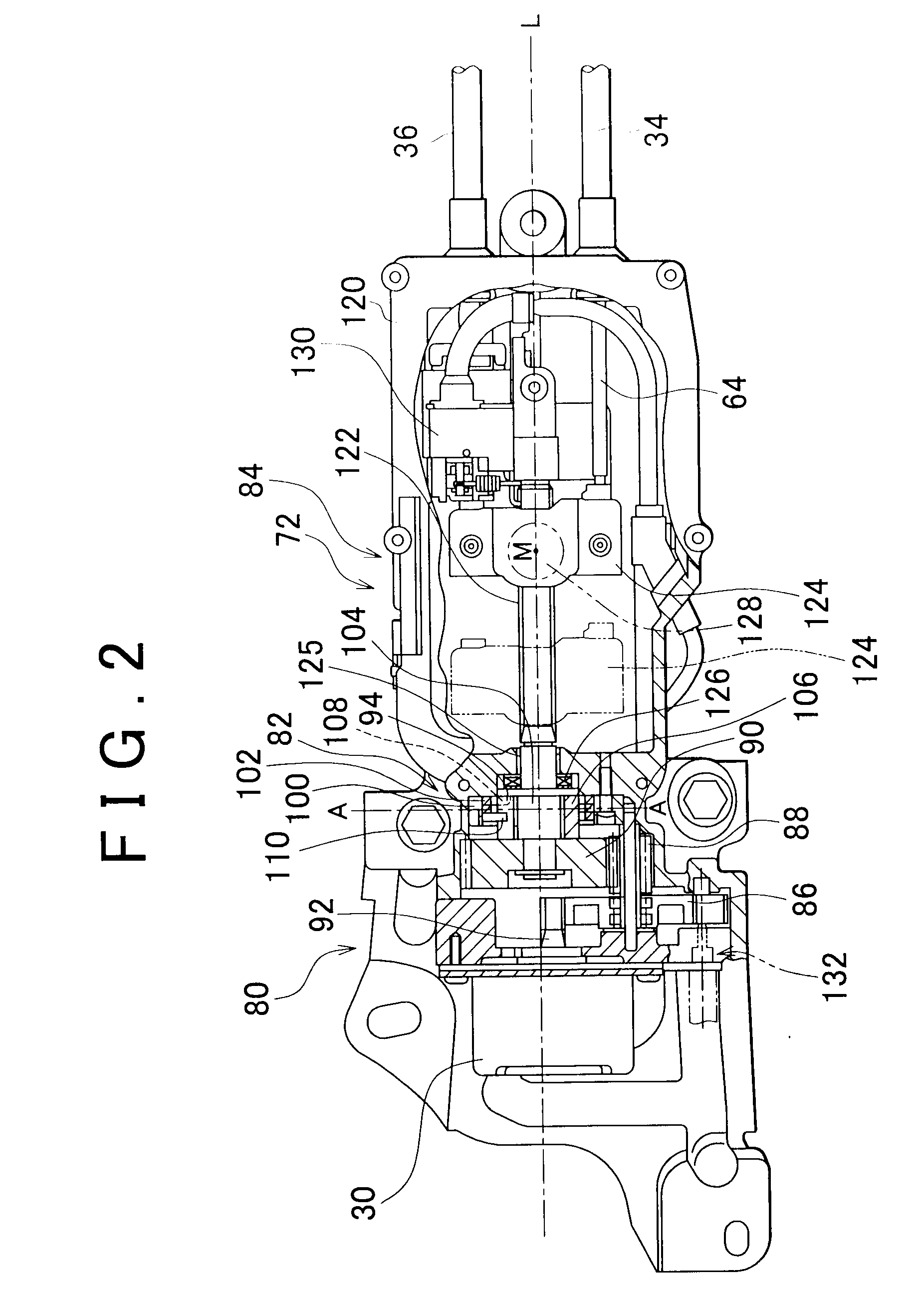
[0046]Hereafter, a vehicle parking system according to an embodiment of the invention will be described with reference to the accompanying drawings. FIG. 1 shows an electric parking brake mechanism 10 and an electric parking lock mechanism 12. As shown in FIGS. 1 to 4, the electric parking brake mechanism 10 includes brakes 18 and 20 that are provided to a rear left wheel 14 and a rear right wheel 16 of the vehicle, respectively, and a pushing unit 32 that includes a second electric motor 30 that serves as a second electromagnetically-driven actuator (hereinafter, referred to as “brake motor 30”). In the electric parking brake mechanism 10, cables 34 and 36 are pulled in response to an operation of the brake motor 30, whereby the brakes 18 and 20 are applied. In the embodiment of the invention, the brakes 18 and 20 are drum brakes that serve as friction brakes, as shown in FIG. 4. The drum brakes 18 and 20 have the same structure. The drum brakes 18 and 20 each include a backing pla...


PUM


Abstract

In a vehicle parking system, when a selected shift position is changed between Park and a shift position other than Park, if both an electric motor of an electric parking lock mechanism and an electric motor of an electric parking brake mechanism are operated, these electric motors are started in such a manner that the times at which striking currents supplied to these electric motors reach their peaks are staggered.

Description

[0001]The disclosure of Japanese Patent Application No. 2007-054682 filed on Mar. 5, 2007 including the specification, drawings and abstract is incorporated herein by reference in its entirety.BACKGROUND OF THE INVENTION[0002]1. Field of the Invention[0003]The invention relates to a vehicle parking system and a method for controlling the same. More specifically, the invention relates to a control over multiple electromagnetically-driven actuators in a vehicle parking system that includes multiple devices.[0004]2. Description of the Related Art[0005]Japanese Patent Application Publication No. 2006-162022 (JP-A-2006-162022) describes a parking brake system in which an electric motor is rotated to operate a parking brake mechanism when the shift position selected by a shift position selection device is Park. Japanese Patent Application Publication No. 2006-27415 (JP-A-2006-27415) describes a parking brake system in which an electric motor is rotated to apply parking brakes when the shi...

Claims


Application Information

Patent Timeline
IPC IPC(8): B60L7/00B60T1/06B60T8/00F16D65/14F16D65/28F16H63/34
CPCB60T1/005B60T13/746B60T2201/06B60W30/18054F16H63/486B60W2510/186F16H63/3416F16H63/3466B60W30/18109
Inventor FUJITA, KOZO
Owner TOYOTA JIDOSHA KK
Why Eureka
Try Eureka