Radar

a radar and radar technology, applied in the field of radars, can solve the problems of affecting the detection of targets while a frequency is being changed, affecting the detection accuracy of targets, etc., and achieves the effect of high noise and high noise sta

Inactive Publication Date: 2008-09-11
MURATA MFG CO LTD
View PDF1 Cites 29 Cited by
  • Summary
  • Abstract
  • Description
  • Claims
  • Application Information

AI Technical Summary

Benefits of technology

[0014](1) Even in the case where spike noise due to interference is superimposed on a beat signal, if the signal strength of a reflected wave is high, peaks having high peak values appear in a frequency spectrum of the beat signal. Thus, by extracting a predetermined number of peaks from the frequency spectrum in descending order starting from the one having the highest peak value, the extracted peaks can be treated as peaks (target peaks) generated due to reception of reflected waves from a target, thereby the target can be detected even at the timing where interference occurs.
[0015](2) In ordinary cases, peaks exceeding a predetermined noise threshold in a frequency spectrum are extracted as target peaks, and beams which are close to each other in an azimuthal direction are compared when electromagnetic wave beams have been scanned over a predetermined direction range. By comparing the beams which are close to each other in the azimuthal direction, if the number of peaks exceeding the threshold has significantly increased, a subject beam is assumed to be in a high noise state, and if the number of peaks exceeding the threshold has significantly decreased, a compared beam is assumed to be in a high noise state. In another case, by comparing the same beams in recent scans, if the number of peaks exceeding the threshold has significantly increased, a high noise state is assumed to be occurring. If the high noise state is assumed, a predetermined number of peaks are extracted from a frequency spectrum in descending order starting from the one having the highest peak value. Thus, target peaks which should be processing targets can be extracted completely in an ordinary state where no interference occurs, and only important target peaks can be extracted and processed in the state where interference occurs.
[0016](3) In ordinary cases, peaks exceeding a predetermined noise threshold in a frequency spectrum are extracted as target peaks. By comparing recent modulation zones, if the number of peaks exceeding the threshold has significantly increased, a subject modulation zone is assumed to be in a high noise state, and if the number of peaks exceeding the threshold has significantly decreased, a compared modulation zone is assumed to be in a high noise state and a predetermined number of peaks are extracted from a frequency spectrum in descending order starting from the one having the highest peak value. Thus, target peaks which should be processing targets can be extracted completely in an ordinary state where no interference occurs, and only important target peaks can be extracted and processed in the state where interference occurs.
[0017](4) In ordinary cases, peaks exceeding a noise threshold in a frequency spectrum are extracted. When it has detected that spike noise is superimposed on a beat signal, a predetermined number of peaks are extracted from a frequency spectrum in descending order starting from the one having the highest signal strength. Thus, target peaks which should be processing targets can be extracted completely in an ordinary state where no interference occurs, and only important target peaks can be extracted and processed in the state where interference occurs.
[0018](5) When a plurality of noise thresholds for extracting a peak having a high peak value from the frequency spectrum are discretely set one after another in descending order, peaks having high peak values are extracted on the basis of a previous noise threshold immediately preceding a noise threshold that has caused the number of peaks exceeding the threshold to increase significantly. Therefore, a large number of proper target peaks can be extracted without extracting a large number of erroneous peaks generated due to interference.

Problems solved by technology

There has been a disadvantage with FM-CW radars using millimeter radio waves as car-mounted radars in that FM-CW radars interfere with radars mounted on other cars.
However, an FM-CW radar needs a wide frequency band in order to perform frequency modulation; therefore, changing a frequency is substantially difficult because of oscillator characteristics or legislation.
In addition, targets cannot be detected while a frequency is being changed.
Furthermore, because, for example, a cycle period of the beam scanning in an azimuthal direction becomes inconstant due to a change in a frequency, problems may occur in functions such as examining the correlation between frequency spectra of the beat signals of beams in the same direction, assuming targets having a strong correlation as the same target, and thereby tracking the target.

Method used


Image

  • Radar
  • Radar
  • Radar

Examples


first embodiment

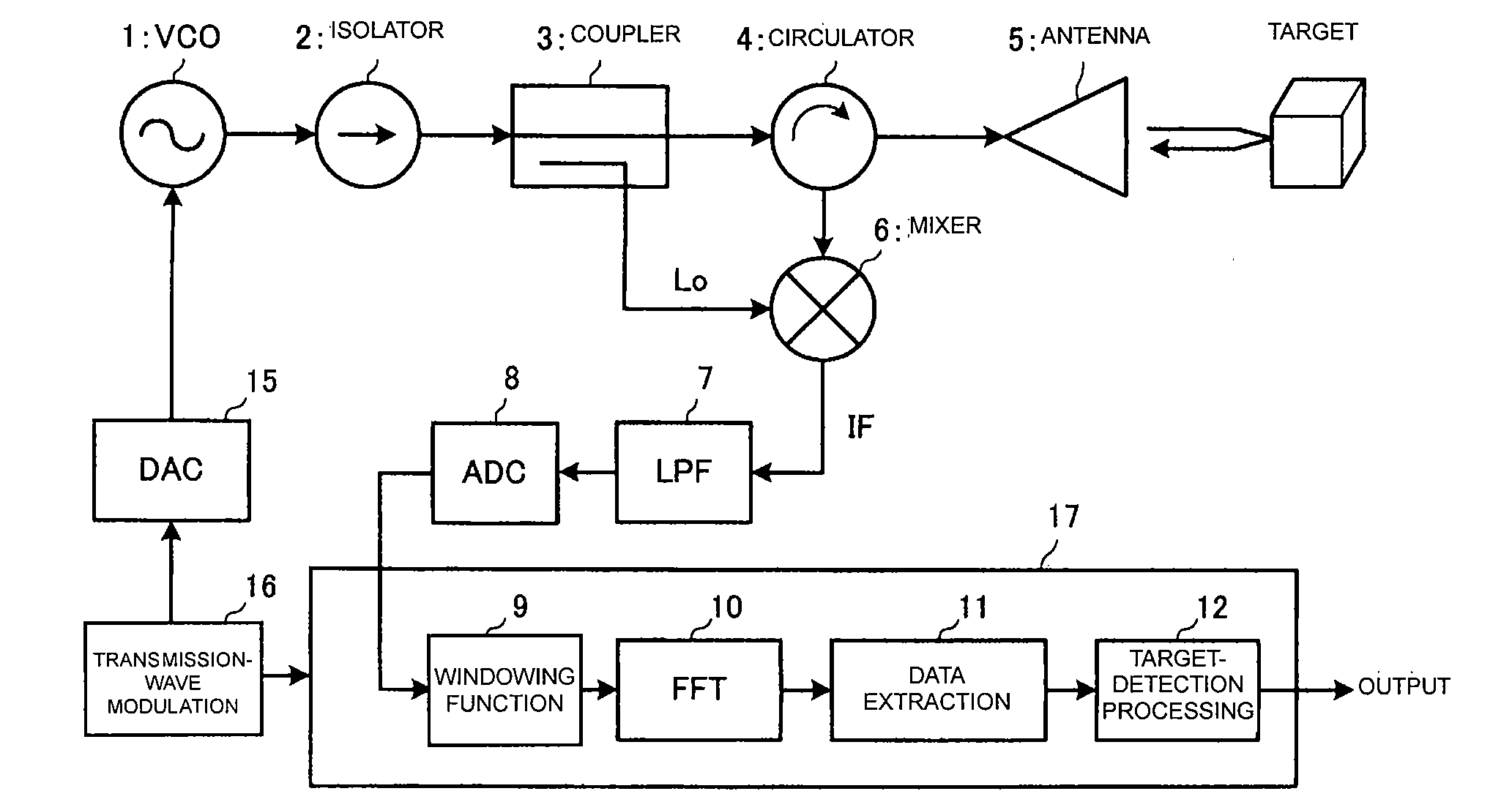
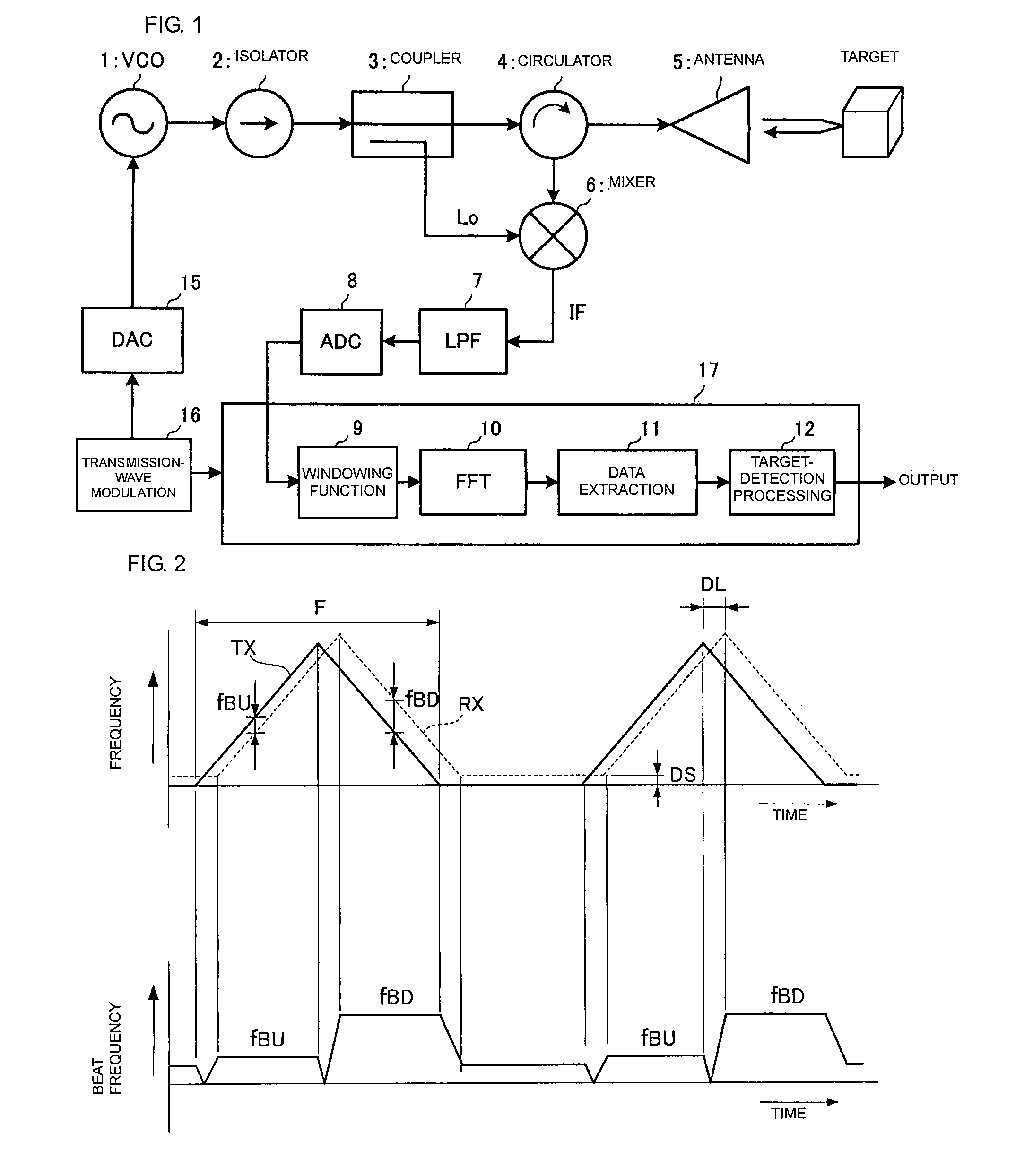
[0038]A structure of a radar will be described with reference to FIGS. 1 through 8.

[0039]FIG. 1 is a block diagram showing an overall structure of a radar. A transmission-wave-modulating unit 16 sequentially outputs digital data of a modulated signal to a DA converter 15. A VCO 1 changes an oscillation frequency on the basis of a control voltage output from the DA converter 15. Thus, the oscillation frequency of the VCO 1 is FM modulated successively in a triangular wave manner. An isolator 2 transmits an oscillation signal received from the VCO 1 to a coupler 3 and prevents a reflection signal from entering the VCO 1. The coupler 3 transmits the signal which has been routed through the isolator 2 to a circulator 4 and supplies a part of the transmission signal, the part being selected from the transmission signal with a predetermined partition ratio, as a local signal Lo to a mixer 6. The circulator 4 transmits the transmission signal to an antenna 5 and supplies a reception signa...

second embodiment

[0055]Next, a radar will be described with reference to FIGS. 9 through 11.

[0056]FIG. 9 is a block diagram showing an overall structure of a radar. A threshold-setting unit 14 sets a noise threshold in order to extract peaks greater than or equal to the noise threshold as the target peaks when the data extraction unit 11 extracts predetermined peaks from the frequency spectrum. The rest of the structure is similar to that shown in FIG. 1.

[0057]FIG. 10 shows a position of a peak appearing in (extracted from) the frequency spectrum of each beam in the case where electromagnetic wave beams are scanned in the azimuthal direction, and the peak position is indicated by a black dot as a position in the propagation direction of the beam.

[0058]Here, a beam Ba is the beam which has been affected by interference. If peaks are extracted from the frequency spectrum using a stationary threshold regardless of whether interference has occurred, many erroneous peaks are extracted as shown in part (...

third embodiment

[0066]Next, a radar will be described with reference to FIGS. 12 and 13.

[0067]FIG. 12 is a block diagram showing an overall structure of a radar. A spike-noise-detecting unit 13 detects whether spike noise is superimposed on a beat signal or not. A threshold-processing and peak-detecting unit 18 performs processing for setting a noise threshold and processing for peak detection in accordance with detection of the presence or absence of a spike noise as described below.

[0068]The threshold-setting unit 14 sets a stationary (the state in which no interference occurs) noise threshold in order to extract peaks greater than or equal to the noise threshold as target peaks when the threshold-processing and peak-detecting unit 18 extracts predetermined peaks from a frequency spectrum. The rest of the structure is similar to that shown in FIG. 1.

[0069]FIG. 13 is a flowchart showing processing steps of target-peak extraction.

[0070]First, spike-noise detection is performed (S41). If spike nois...


PUM


Abstract

A radar wherein, in response to an increase in the level of noise appearing in a frequency spectrum caused by interference being superimposed on a beat signal, peaks exceeding a threshold are extracted as target peaks in an ordinary state and a predetermined number of peaks in descending order starting from the peak having the highest peak value are extracted in the case where interference occurs.

Description

CROSS REFERENCE TO RELATED APPLICATIONS[0001]The present application is a continuation of International Application No. PCT / JP2006 / 307540, filed Oct. 4, 2006, which claims priority to Japanese Patent Application No. JP2005-141932, filed May 13, 2005, the entire contents of each of these applications being incorporated herein by reference in their entirety.FIELD OF THE INVENTION[0002]The present invention relates to an FM-CW radar which detects a target by transmitting and receiving an electromagnetic beam wave.BACKGROUND OF THE INVENTION[0003]There has been a disadvantage with FM-CW radars using millimeter radio waves as car-mounted radars in that FM-CW radars interfere with radars mounted on other cars. That is, as shown in part (A) of FIG. 4, when a subject car MM on which a radar of a type in which beams are scanned in an azimuthal direction is mounted faces an object car OM1 of the same type, spike noise is superimposed on (mixed with) a beat signal at the timing of generating a...

Claims


Application Information

Patent Timeline
Patent Type & Authority Applications(United States)
IPC IPC(8): G01S13/00G01S13/931
CPCG01S7/354G01S7/414G01S2007/356G01S13/931G01S13/345G01S7/356
Inventor NAKANISHI, MOTOI
Owner MURATA MFG CO LTD
Why Eureka
Try Eureka