Patch antenna including septa for bandwidth conrol

a patch antenna and bandwidth conrol technology, applied in the direction of resonant antennas, substantially flat resonant elements, radiating element structural forms, etc., can solve the problems of increasing the thickness of the antenna, increasing the lateral size of the antenna, and the device's relatively narrow bandwidth, so as to reduce the total cavity thickness, increase mutual coupling, and allow the effect of bandwidth control

Active Publication Date: 2008-09-11
LOCKHEED MARTIN CORP
View PDF4 Cites 89 Cited by
  • Summary
  • Abstract
  • Description
  • Claims
  • Application Information

AI Technical Summary

Benefits of technology

[0012]A patch antenna element includes a parasitic patch which is positioned on a top surface of a substrate. Located beneath the parasitic patch is a driven patch. The driven patch is coupled either directly or capacitively to the center conductor of a coaxial cable and hence provides a signal which signal is coupled to the parasitic patch. The parasitic patch, as well as the driven patch is surrounded by a metal wall cavity

Problems solved by technology

However, one drawback of such devices is their relatively narrow bandwidth.
However, the antenna substrate supports tightly bound surface wave modes which represent a loss mechanism in the antenna.
However, this has the disadvantage of

Method used


Image

  • Patch antenna including septa for bandwidth conrol
  • Patch antenna including septa for bandwidth conrol
  • Patch antenna including septa for bandwidth conrol

Examples


Embodiment Construction

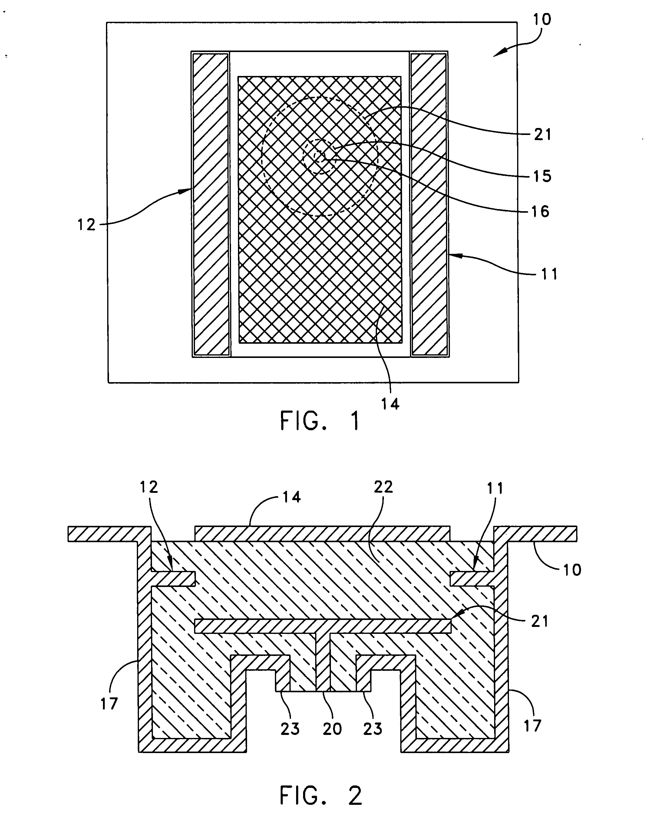
[0026]Referring to FIG. 1, there is shown a top plan schematic view of a patch antenna employing septa according to an exemplary embodiment of this invention. Reference numeral 10 refers to a metal housing cavity which contains a patch antenna. In an exemplary embodiment, the metal housing cavity comprises a metallized surface electro-plated on a plastic or composite core dielectric. The patch antenna has a top metal patch 14 which is disposed and positioned on the surface of a dielectric material. Beneath the patch, there is a shown a coaxial transmission line consisting of a center conductor 16 surrounded by a shield 15. The patch 14 as indicated is disposed upon the surface of a dielectric material. The septa are shown as elements 11 and 12. Each septum as will be more clearly seen in FIG. 2, is positioned between a top parasitic patch (identified as patch 14) and a bottom direct driven patch (identified as patch 21). Referring to FIG. 2, the septa 11, 12 are positioned midway be...


PUM


Abstract

A patch antenna element includes a parasitic patch which is positioned on a top surface of a substrate. Located beneath the parasitic patch is a driven patch. The driven patch is coupled either directly or capacitively to the center conductor of a coaxial cable and hence provides a signal which signal is coupled to the parasitic patch. The parasitic patch, as well as the driven patch is surrounded by a metal wall cavity. The metal wall cavity increases mutual coupling between antenna patch elements of similar types. Disposed between the parasitic patch and the driven patch are septa elements. The septa elements are oriented parallel to the edges of the patch and are DC connected to the cavity metal sidewalls. The septa operate to reduce total cavity thickness and patch to patch mutual coupling while further allowing control of the bandwidth.

Description

RELATED APPLICATION[0001]This application is a continuation-in-part of co-pending application Ser. No. 11 / 713,914 filed on Mar. 5, 2007, entitled “TUNING APPARATUS FOR A PROBE FED PATCH ANTENNA”, the subject matter thereof incorporated by reference herein.FIELD OF THE INVENTION[0002]The present invention relates to a microstrip antenna and more particularly to a microstrip antenna or patch antenna with septa for bandwidth control, and reduction of antenna element thickness.BACKGROUND OF THE INVENTION[0003]Microstrip patch antennas have several well known advantages over other antenna structures. These antennas generally have a low profile and conformal nature, are lightweight, have low production cost, are robust in nature and compatible with microwave monolithic integrated circuits (MMICs) and optoelectronic integrated circuits (OEICs) technologies. However, one drawback of such devices is their relatively narrow bandwidth. In order to achieve wider bandwidth, a relatively thick su...

Claims


Application Information

Patent Timeline
IPC IPC(8): H01Q1/38H01Q9/04
CPCH01Q1/38H01Q13/18H01Q9/0414H01Q9/045
Inventor GILLETTE, MARLIN R.
Owner LOCKHEED MARTIN CORP
Why Eureka
Try Eureka