
Vehicular control apparatus and control system

Inactive Publication Date: 2008-09-11
TOYOTA JIDOSHA KK
View PDF5 Cites 36 Cited by
  • Summary
  • Abstract
  • Description
  • Claims
  • Application Information

AI Technical Summary

Benefits of technology

[0017]This invention provides a vehicular control apparatus and control method which reduces shock during synchronization by suppressing an increase in torque of an inertia portion during an inertia phase when a power-off downshift is performed in a vehicle that outputs power from an electric motor to an output shaft (i.e., driving wheels) via an automatic transmission.
[0019]According to this aspect, instead of normally making the input of the automatic transmission constant power during the inertia phase when a power-off downshift is being performed, the output torque of the electric motor is controlled so that the input torque of the automatic transmission is constant (i.e., constant torque). As a result, shock that occurs upon the completion of synchronization can be suppressed.
[0021]According to the invention, when a power-off downshift is performed, the output torque of the electric motor is controlled so that the input torque of the automatic transmission is constant torque during the inertia phase of that shift. As a result, the torque of the inertia portion during the inertia phase can be kept substantially constant. Accordingly, the change in the output torque during synchronization by the apply-side friction apply element can be kept to a minimum without performing complicated hydraulic pressure control, which enables shock that occurs during synchronization to be significantly reduced. Moreover, the negative torque during the inertia phase can be increased which enables the amount of power (i.e., electricity) that is regenerated to be increased, i.e., enables fuel efficiency to be improved.

Problems solved by technology

As a result, a shock occurs upon the completion of synchronization.
However, in reality it is difficult to execute control that accurately reduces the clutch torque Tcapl once it has increased.
However, because the increase in the motor torque is complete before the shift is complete (i.e., before the rotation is synchronized by the apply-side apply element), shift shock may occur.
Also, with the technology described in JP-A-2006-056343, it is not possible to resolve the problem caused by the increase in the torque of the inertia portion [I(dω / dt)] during the inertia phase.

Method used


Image

  • Vehicular control apparatus and control system
  • Vehicular control apparatus and control system
  • Vehicular control apparatus and control system

Examples


Embodiment Construction

[0033]In the following description and the accompanying drawings, the present invention will be described in more detail in terms of example embodiments.

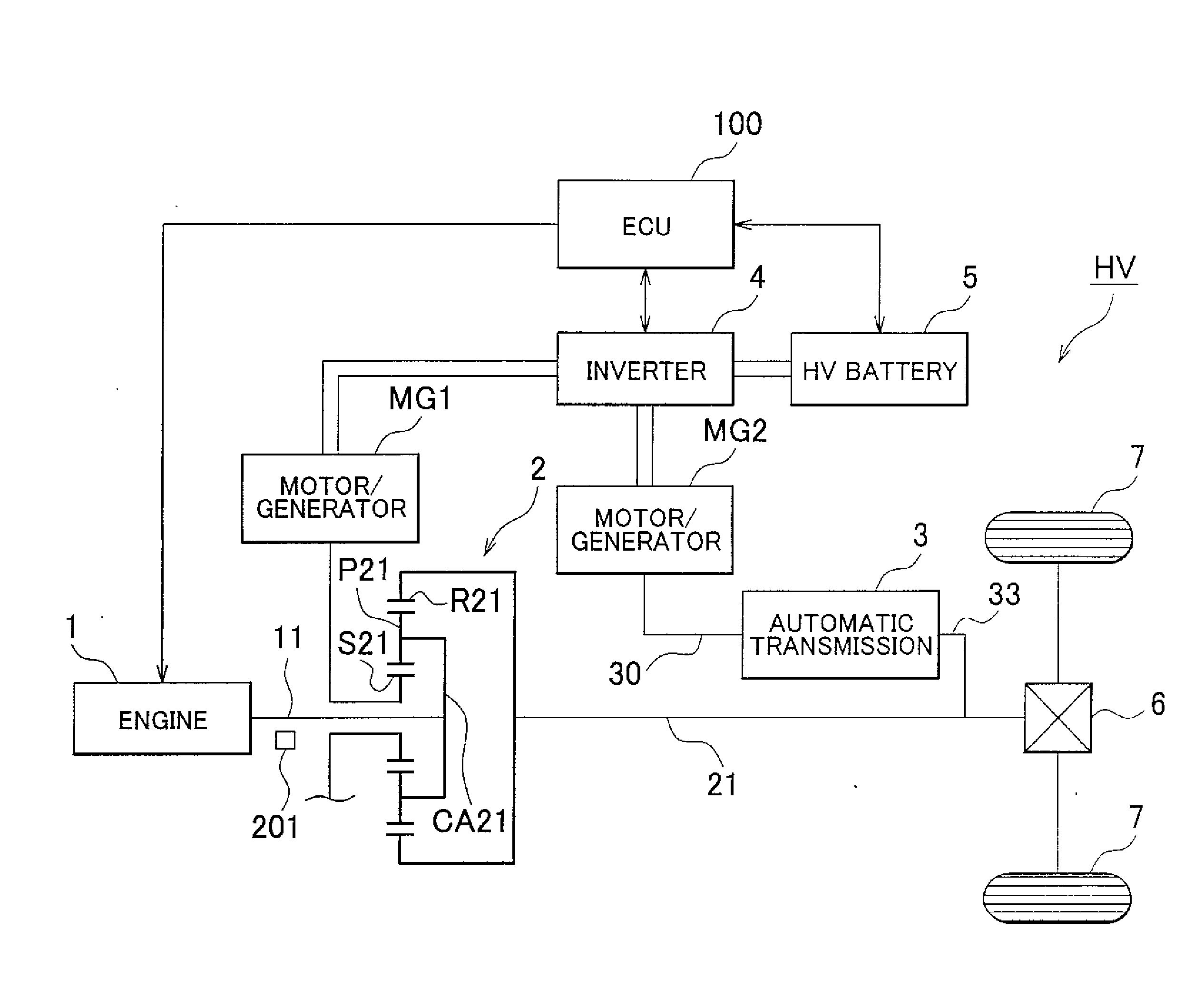
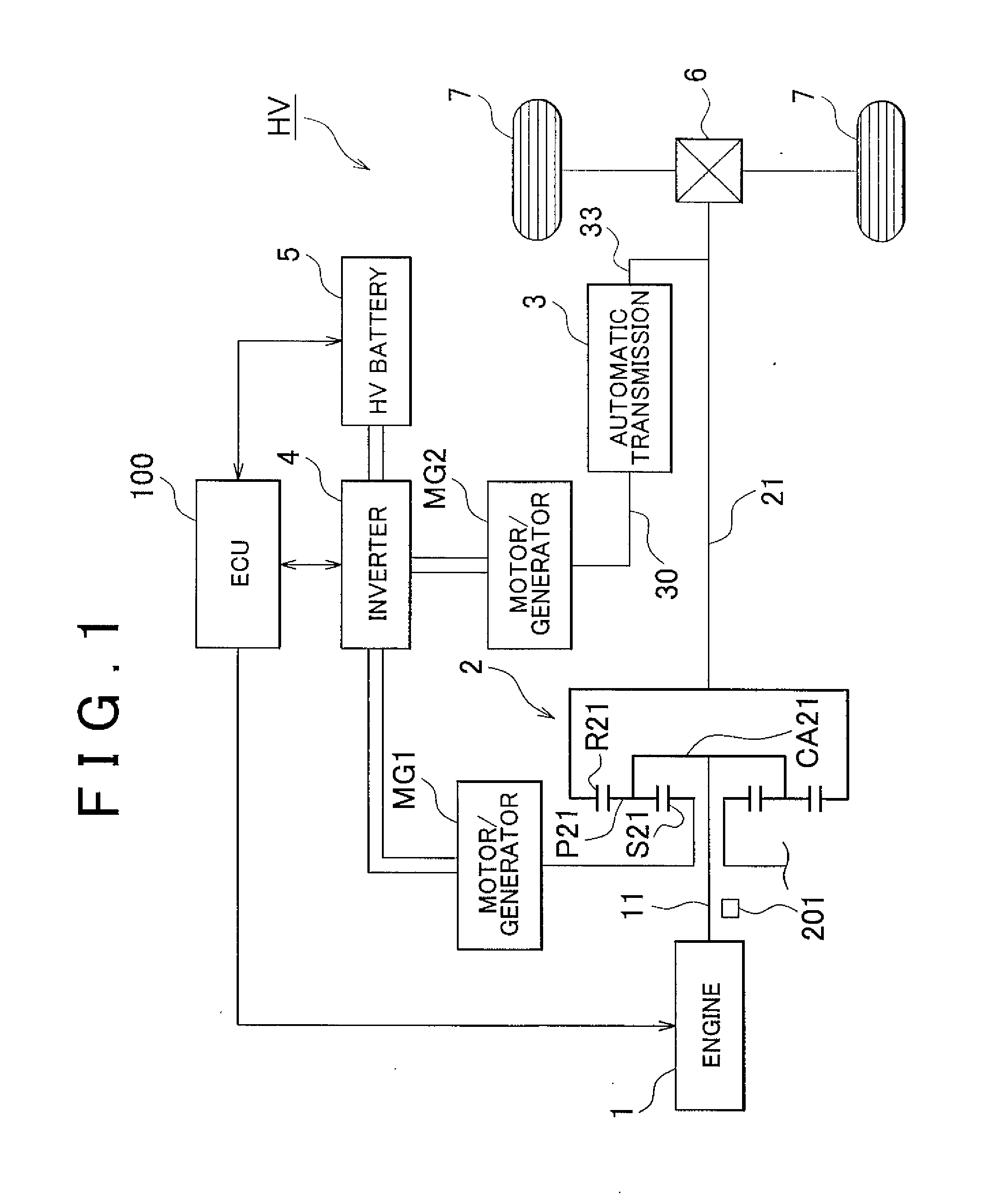
[0034]FIG. 1 is a block diagram schematically showing an example of a hybrid vehicle to which a control apparatus according to an example embodiment of the invention can be applied.

[0035]The hybrid vehicle HV shown in FIG. 1 is provided with an engine 1, a motor / generator MG1, a motor / generator MG2, a power transmitting mechanism 2, an automatic transmission 3, an inverter 4, a HV battery 5, a differential gear 6, driving wheels 7, and an ECU (Electronic Control Unit) 100 and the like.

[0036]Each of these will now be described.

[0037]The engine 1 is a known powering apparatus such as a gasoline engine or a diesel engine that outputs power by burning fuel, and is structured such that the operating state, e.g., the throttle opening amount (i.e., intake air amount), the fuel injection quantity, and the ignition timing and the like, can b...


PUM


Abstract

A control apparatus for a vehicle is provided with an electric motor that outputs driving force for running the vehicle; an automatic transmission that establishes a plurality of gears by selectively applying and releasing a plurality of friction apply elements in a predetermined combination for each gear among the plurality of gears, and transmits power from the electric motor to an output shaft of the vehicle; and a torque controlling portion which, when there is a demand for a power-off downshift, controls output torque of the electric motor such that input torque of the automatic transmission becomes constant torque during an inertia phase of that shift, and controls the output torque of the electric motor such that the output torque of the automatic transmission comes to match the torque required after the shift, after rotation synchronization by an apply-side friction apply element is complete.

Description

INCORPORATION BY REFERENCE[0001]The disclosure of Japanese Patent Application No. 2007-058736 filed on Mar. 8, 2007, including the specification, drawings and abstract is incorporated herein by reference in its entirety.BACKGROUND OF THE INVENTION[0002]1. Field of the Invention[0003]The invention relates to a control apparatus and control method of a vehicle such as a hybrid vehicle which has an electric motor that outputs driving force for running the vehicle, and an automatic transmission that establishes a plurality of gears by selectively applying and releasing a plurality of friction apply elements in a predetermined combination for each gear among the plurality of gears. More particularly, the invention relates to a vehicular control apparatus and control method of a vehicle which outputs power from the electric motor to an output shaft (i.e., driving wheels) via the automatic transmission.[0004]2. Description of the Related Art[0005]In recent years, there has been a demand fo...

Claims


Application Information

Patent Timeline
IPC IPC(8): B60W10/08B60W10/10B60K6/445B60K6/547B60L15/20B60W20/00F16H59/68F16H61/04F16H61/68F16H61/684F16H61/686F16H63/40F16H63/50
CPCB60K1/02Y10T477/347B60K6/365B60K6/445B60K6/547B60L2240/423B60L2240/441B60L2240/486B60W10/06B60W10/08B60W10/115B60W20/00B60W2510/0604B60W2510/0638B60W2510/1005B60W2510/1015B60W2510/104B60W2520/10B60W2540/10B60W2710/0644B60W2710/083B60W2710/1022F16H2037/0873Y02T10/6286Y02T10/642Y02T10/7258Y02T10/6239Y10T477/23B60K6/26Y02T10/62Y02T10/64Y02T10/72B60W2510/1025B60W2710/027B60W10/10B60W2510/105
Inventor MAEDA, YASUHIRO
Owner TOYOTA JIDOSHA KK
Learn More