Multi-electrode stimulation to elicit electrically-evoked compound action potential

a multi-electrode, compound action potential technology, applied in electrotherapy, therapy, etc., can solve the problems of inability to provide meaningful subjective feedback, inability to fully control and customize the operation of the cochlear, and the implanted portion of the cochlear stimulation system. to achieve the effect of better determining the appropriate intensity threshold level

Inactive Publication Date: 2008-09-11
ADVNACED BIONICS LLC
View PDF27 Cites 79 Cited by
  • Summary
  • Abstract
  • Description
  • Claims
  • Application Information

AI Technical Summary

Benefits of technology

[0027]It is thus a feature of the present invention to provide an improved system and method of fitting a neurostimulator device by measuring the ECAP of the patient through application of multi-band (i.e., multi-electrode contact) stimulation in order to better determine appropriate intensity threshold levels used by the implant system during its operation.
[0028]It is a further feature of the invention to provide such an improved system and method of fitting that does not require subjective feedback from the patient during the fitting procedure.
[0029]It is an additional feature of the invention to provide an improved technique for evoking a compound action potential for the purpose of validating proper operation of the implant device at a time shortly after the device is implanted at a time when the patient may still be under the influence of an anesthesia, and hence unconscious.

Problems solved by technology

There are cases where such application of a stimulus to a single electrode contact do not evoke a suitable action potential.
One of the problems encountered when using a cochlear implant device, or many other type of neurostimulator devices, is “fitting” the device to a particular patient.
Some patients, however, e.g., old patients and extremely young patients, are not able to provide meaningful subjective feedback.
As the art of cochlear stimulation has advanced to produce bionic ear implants, the implanted portion of the cochlear stimulation system, and the externally wearable processor (or speech processor) have become increasingly complicated and sophisticated.
The amount of control and discretion exercisable by an audiologist in selecting the modes and methods of operation of the cochlear stimulation system have increased dramatically and it is no longer possible to fully control and customize the operation of the cochlear stimulation system through the use of, for example, switches located on the speech processor.
Disadvantageously, determining the “T” and / or “M” levels (or other required thresholds) associated with each channel of a multichannel stimulation system is an extremely painstaking and time-intensive task.
Such determinations require significant time commitments on the part of the clinician, as well as the patient.
Moreover, once determined one channel at a time, such levels may not be representative of actual threshold levels that are present during real speech.
Such an overestimation appears to penalize patient performance, particularly performance in noise.
This is because very young patients, for example, two year olds, are unable to provide adequate subjective feedback to the audiologist for the audiologist to accurately “fit” the cochlear stimulation system optimally for the patient.
Such subjective feedback can be highly unreliable, particularly in younger and older patients.
Disadvantageously, there are cases where it is difficult to obtain neural response measurements, e.g., an ECAP, on a given patient.
That is, the delivery of a stimulus pulse on a single electrode contact may fail to synchronize enough neural fibers to produce a measurable evoked response.

Method used


Image

  • Multi-electrode stimulation to elicit electrically-evoked compound action potential
  • Multi-electrode stimulation to elicit electrically-evoked compound action potential
  • Multi-electrode stimulation to elicit electrically-evoked compound action potential

Examples


Embodiment Construction

[0040]The following description is of the best mode presently contemplated for carrying out the invention. This description is not to be taken in a limiting sense, but is made merely for the purpose of describing the general principles of the invention. The scope of the invention should be determined with reference to the claims.

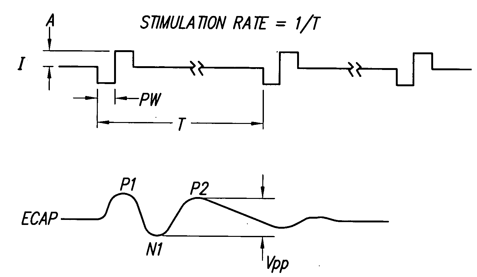
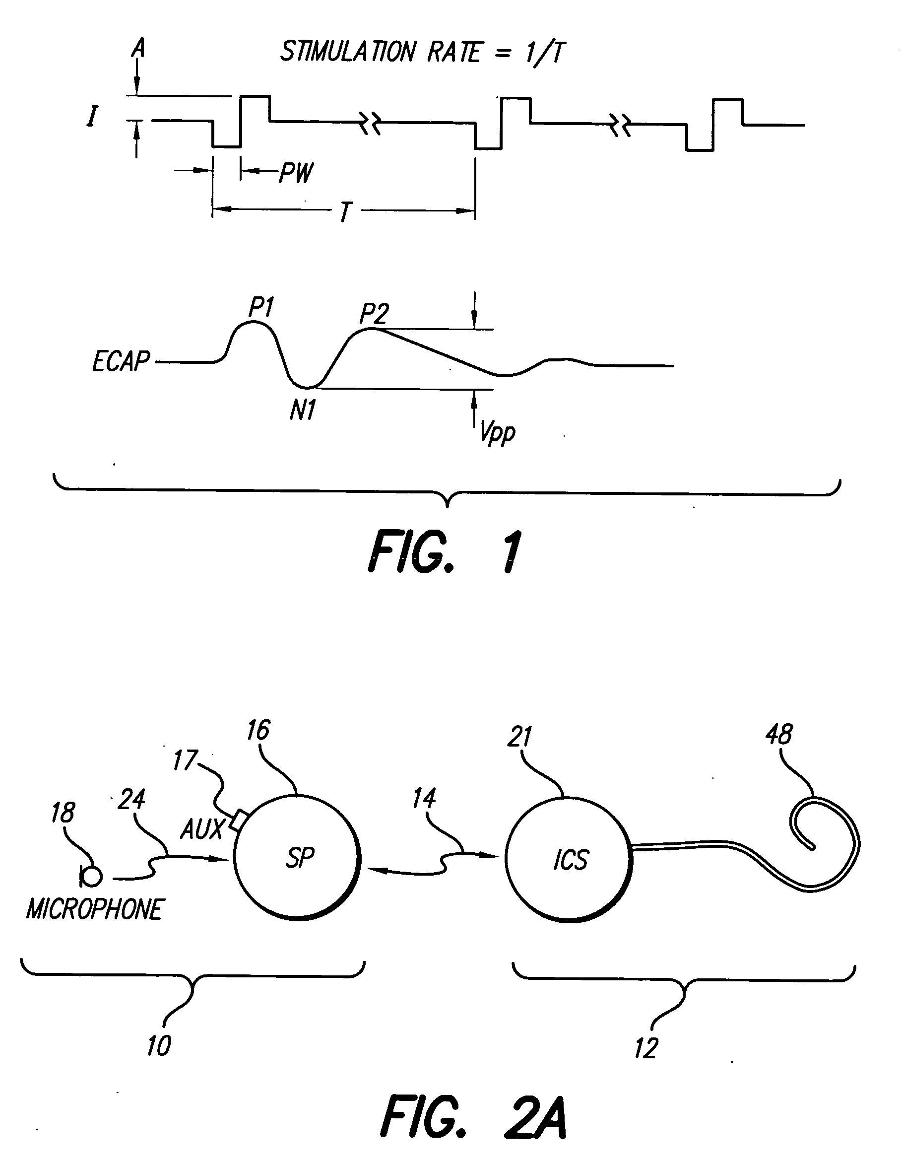
[0041]FIG. 1 shows a current stimulation waveform (I) and a corresponding evoked compound action potential (ECAP). FIG. 1 defines the stimulation rate (1 / T), amplitude (A) and biphasic pulse width (PW) associated with the current stimulation waveform. FIG. 2 also illustrates a typical ECAP waveform that is evoked in response to the applied current stimulation waveform. Such ECAP waveform is typically characterized by three humps, or peaks, labeled P1, N1, and P2. The first peak P1 is, as illustrated in FIG. 1, a positive peak and is often difficult to measure, as it may be swamped out by other electrical activity. The second peak N1, as illustrated in FIG. 1...


PUM


Abstract

A multichannel neurostimulation device spatially spreads the excitation pattern in the target neural tissue by either: (1) rapid sequential stimulation of a small group of electrodes, or (2) simultaneously stimulating a small group of electrodes. Such multi-electrode stimulation stimulates a greater number of neurons in a synchronous manner, thereby increasing the amplitude of the extra-cellular voltage fluctuation and facilitating its recording. The electrical stimuli are applied simultaneously (or sequentially at a rapid rate) on selected small groups of electrodes while monitoring the evoked compound action potential (ECAP) on a nearby electrode. The presence of an observable ECAP not only validates operation of the implant device at a time when the patient may be unconscious or otherwise unable to provide subjective feedback, but also provides a way for the magnitude of the observed ECAP to be recorded as a function of the amplitude of the applied stimulus. From this data, a safe, efficacious and comfortable threshold level can be obtained which may be used thereafter as the initial setting of the stimulation parameters of the neurostimulation device, or to guide the setting of the stimulation parameters of the neurostimulation device.

Description

[0001]The present application claims the benefit of U.S. Provisional Patent Application Ser. No. 60 / 425,215, filed Nov. 8, 2002.BACKGROUND OF THE INVENTION[0002]The present invention relates to neurostimulator implant devices, and more particularly to a system and method that uses multi-electrode stimulation provided by a neurostimulator implant device to elicit electrically-evoked compound action potentials. Such an evoked compound action potential (ECAP) provides valuable objective feedback information useful in setting the stimulation parameters associated with the neurostimulator implant device.[0003]Traditional methods used to elicit the electrically-evoked compound action potential, or ECAP, deliver stimulation to a single electrode contact. There are cases where such application of a stimulus to a single electrode contact do not evoke a suitable action potential. The present invention provides an improved system and method for obtaining the ECAP through application of the sti...

Claims


Application Information

Patent Timeline
Patent Type & Authority Applications(United States)
IPC IPC(8): A61N1/00
CPCA61N1/37247A61N1/36032A61N1/36039
Inventor OVERSTREET, EDWARD H.LITVAK, LEONID M.FALTYS, MICHAEL A.
Owner ADVNACED BIONICS LLC
Why Eureka
Try Eureka